


Long-load Bogie
Page 78
If you've noticed an error in this article please click here to report it so we can fix it.
ASPECIAL vehicle covered by patent the carriage of long loads. The rear separate steerable bogie. (G. Hougharn Church Road, Hayes, Middlesex.
The rigid vehicle carrying the front of universal swivelling bolster which allows
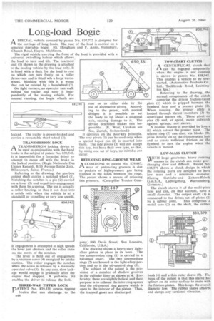
the load to turn and tilt. The rearmost unit (1) shown in the drawing is attached• to the leading vehicle by the load only. It is fitted with a deck for the load to rest on which can turn freely on a roller thrust-race and is fitted wih a large wormwheel. Meshing with this is a worm that can be rotated by a handwheel (2).
On tight corners, an operator can walk behind the trailer and steer it independently of the leading vehicle. For normal running, the bogie wheels are locked. The trailer is power-braked and carries a retractable third wheel (3).
TRANSMISSION LOCK A TRANSMISSION locking device to PIbe used in conjunction with the hand brake is the subject of patent No. 839,540. It is impossible for a forgetful driver to attempt to move off with the brake in the locked position. (Regie Nationale Des Usines Renault, 8/10 Avenue Emile Zola, 13illancourt, Seine, France.) Referring to the drawing, the gearbox output shaft carries a notched wheel (1). Matching the notches is a pin (2) carried on a lever (3) and urged into engagement with them by a spring. The pin is actually a roller bearing, so that it can drop into a notch only when the vehicle is at a standstill or travelling at very low speeds.
If engagement is attempted at high speeds the lever just chatters and the roller rides on the crests of the notches.
The lever is held out of engagement by a vacuum servo (4) energized by intake suction. The roller engages the notches when the servo is released by a manually operated valve (5). In any case, slow leakage would engage it gradually after the engine had stopped. A pull-wire (6) enables the driver to release the lock.
rear or to either side by the use of alternative pivots. According to the patent, with normal designs it is possible to set the body to tip about a diagonal axis, causing damage to it. The device described makes this impossible. (E. Wirz, Uetikon am . See, Zurich, Switzerland.)
I operates on the door-key principle. The rear pivots (I) can be used only when a special keyed pin (2) is inserted into them. The side pivots (3) will not accept this key, but have their own type, so that, by using one set of keys, no mistake can occur.
REDUCING RING-GROOVE WEAR
ACCORDING to patent No. 839,447, wear of piston-ring grooves is due to pockets of high-pressure gas being trapped in the lands between the rings. The patent shows a means of relieving this pressure. (Caterpillar Tractor Com
pany, 800 Davis Street, San Leandro, California, U.S.A.) The drawing shows a heavy-duty lightalloy piston in place in its bore. The top compression ring (1) is carried in a hardened insert. The two intermediate rings (2) are housed in the light-alloy portion and so is the oil-control ring (3).
The subject of the patent is the provision of a number of shallow grooves in the cylinder liner as shown at 4. Preferably, these are slightly helical and their purpose is to exhaust the inter-ring spaces into the oil-control ring groove which is open to the interior of the piston. Thus, the trapped gases are discharged. . A CENTRIFUGAL clutch that rA can be engaged . temporarily when the engine is not running is shown in patent No. 838,942. This enables a vehicle to be towstarted. (Automotive Products Co.. Ltd., Tachbrook Road, Learnington Spa.) Referring to the drawing, the normal components of the clutch comprise the driven friction-faced plate (1) which is gripped between the flywheel face and a presser plate (2). When running, the presser plate is loaded through thrust members (3) by centrifugal masses (4). These pivot on pins (5) and, at speed, move outwards against springs, not shown. A manual release is provided by levers (6) which retract the presser plate. The release ring (7) can also, via blocks (8), press directly on to the friction-plate hub and so create sufficient friction on the flywheel to turn the engine when the vehicle is moved.
LOW-MASS CLUTCH WITH large gearboxes heavy rotating IT masses in the clutch can make gearchanging slow and difficult. Patent No. 838.379 shows a clutch design in which the rotating parts are designed to have low mass and a minimum diameter. (Getrag Gctriebe-und Zahnradfabrik G.m.b.H., Ludwigsburg, Wurttemberg, Germany.) The clutch shown is of the multi-plate type and can, on that account, have a small diameter. The output shaft (1) is connected to the driven set of plates (2) by a rubber joint. This comprises a metal core (3) on the shaft, the rubber
bush (4) and a thin outer sleeve (5). The basis of the patent is that this sleeve has splines on its outer surface to mate with the friction plates. This keeps the overall diameter low. The rubber sleeve absorbs and damps any torsional vibration.