


New Principle in Differential Design
Page 66
If you've noticed an error in this article please click here to report it so we can fix it.
T' problem of loss of drive through a differential gear should one of the elements slip is solved in a novel way in a scheme described in patent No. 731,938, by Harry Ferguson Research, Ltd., "Abbotswood," Stow-on-the-Wold, Glos. The scheme is intended mainly for four-wheel-drive vehicles, although it could also be applied to those driving on two.
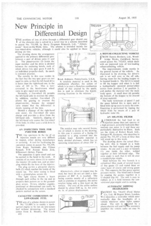
The drawing shows the arrangement applied to the primary differential gear between a pair of driven axles (1 and 2). The planet-carrier (3) forms the input member and the drive is divided between the enclosing bevels, each of which drives (via spur gears 4 and 5), an individual propeller-shaft. So much is common practice.
The novelty in this case resides in the fact that the two spur gears are not equal in ratio, so that the left-hand drive is faster than the right-hand one, in the ratio of 105 to 95. This is later corrected in the bevel-crown wheel ratio to give equal axle speeds.
Normally, a free-wheel (6) permits the left-hand axle to overrun the other. In addition, another free-wheel (7) allows the gearing to overrun the planet-carrier, because the unequal ratio means that the differential is slowly running all the time.
Should a slippage of the right-hand axle occur, the free-wheel (6) takes charge and provides a drive from the left-hand side. Similarly, slipping of the left-hand axle causes the free-wheel (7) to lock; in either case a solid drive is provided.
AN INSPECTION TOOL FOR INJECTOR BORES
THE tiny apertures in the tip of an injection nozzle are very difficult to inspect, either during manufacture or servicing. A tool for facilitating the operation comes in patent No. 731,539, from Regie Nationale des Usines Renault, 8-10 Avenue Emile Zola, Billancourt (Seine), France.
The apparatus is quite small and can be carried in the hand to the work. It consists of an outer sleeve (1) to receive the injector (2) under test, and an inner plug which fits the bore of the injector.
The plug carries a pin-point electric bulb (3) which reaches the inside of the nozzle tip. The outer casing is fitted with a ground-glass screen (4).
The light source throws a beam through each orifice in the tip and so projects their pattern on to the groundglass screen. Errors, whether. angular, positional or dimensional can easily be checked by comparison with a standard pattern marked on the screen.
CATALYTIC COMBUSTION OF LOW-GRADE FUEL
THE aim of a scheme shown in patent No. 731,889,"is to enable a sparkignited engine to be run on low-octane fuef 'without detonating. The patent comes from E. Houdry, Mill Creek
rt32 Road, Ardmorc, Pennsylvania, U.S.A.
A catalytic material is used in the combustion chamber, the action of which is to start a flameless combustion ahead of that created by the spark; this is said to eliminate the knockcreating fractions in the mixture.
The catalyst may take several forms, one of which is shown in the drawing. In tins case it consists of a facing (1) attached to a plug screwed into the cylinder head. Suitable material is finely divided platinum, which has an operating temperature of about 550° F.
Alternatively, silver or copper may be used, but these do not act until a temperature of 800° F. is reached. The facing consists mostly of a refractory such as alumina or magnesia, the active 'catalyst being only a thin layer on the surface. The area of the active surface should be about 0.08 sq. in. for every cu. in. of piston displacement.