


New Light Air-pressure Braking System
Page 45
If you've noticed an error in this article please click here to report it so we can fix it.
9' LIE comparatively heavy components used in
air-pressure braking systems have hitherto precluded the adoption of air-pressure braking on other than the larger commercial vehicles. In a lightweight outfit which is now being produced by Clayton Dcwandre Co., Ltd., Titanic Works, Lincoln. under licence from the American Bendix. Westinghouse concern, suitable equipment is provided for use • on vehicles in the medium-weight range.
Two types of compressor are available, the .essential difference between them being that one has a selfcontained lubricating systent whilst the other k lubricated from the engine.
he two-cylindered air-cooled compressor has a 1.1-in. bore and 1 stroke, the piston displacement being 4 cu. ft. at 1,250 r.p.rin. The maximum operating speed is 3,000 r.p.m. The self-lubricating unit weighs 14 lb. and the alternative type, 12 lb.
There are two departures from standard American practice in the design of the compressor. One is the use of spring-loaded disc inlet valves, which permit the unloader valve mechanism to be simplified. The mechanism itself forms the second departure.
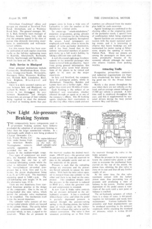
The unloader valve consists of two spring-loaded pistons which are located in the cylinder block. The cavity below the piston communicates with the governor which, in turn, is piped to the reservoir. When the air pressure in The engine-lubricated compressor showing, on the left, the inbuilt unloader-valre mechanism.
the reservoir reaches the desired maximum-100-105 p.s.i.—the governor cuts in and permits air from the reservoir to pass to the unloader cavity and act on the underside of the piston.
Pressure is such that the unloading springs are overcome and the pistons are forced upwards to unseat the inlet valves. With both the inlet valves open, air is pumped from one cylinder to the other and there is no load on the com pressor. This condition obtains until the pressure in the reservoir is reduced to 80-85 p.s.i., when the governor cuts in and compression is resumed.
A new .lype E brake valve controls the air pressure delivered to the airhydraulic actuator, it has a combined inlet-exhaust valve, and when the pedal is partially depressed pressure is exerted through the pressure-setting spring to the floating piston, the hollow stem of which closes on the rubberfaced inlet-exhaust disc valve to seal the exhaust connection. The valve is.then unseated, permitting air to flow from
the reservoir through the valve to the brake actuator.
When the pressure in the actuator and below, the control-valve piston is sufficient to overcome the mechanical force exerted on the top of the piston, the piston rises, allowing the disc valve to close on its seal and shut off any further supply of air.
At the same time, the disc valve maintains' contact with the hollow piston stem. thus preventing loss of pressure and producing a state of balance in the system. Further partial depression of the pedal causes a repetition of the cycle until a new point of balance is reached.
The air-hydraulic actuator, of which there is a range of types, is dirt-proof, requires no lubrication and needs little
maintenance. Various hydraulic linepresstlres and fluid displacements can be produced according to the -actuator employed, whilst retaining the standard air pressure, which is within 85-105
p.s.i. B11