


Converting a Four-wheeler Into a Six-wheeler
Page 66
If you've noticed an error in this article please click here to report it so we can fix it.
A Resume' of Recently Published Patent Specifications
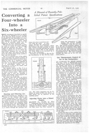
THE attachment described in specification No. 332,222, by E. T. J. Tapp, of 10, Manville Road, London, S.W.17, is intendcd for the conversion bf a fourwheeled vehicle into a six-wheeler by the addition of certain parts, which have to be specially made, and the utilization of many standard parts.
The inventor has, apparently, a popular make of vehicle in mind, although he does not mention any name. The vehicle to which his invention is particularly adapted is one in which the main-frame members are not parallel with each other, but taper towards the front, the springs being of the cantilever type and not parallel.
Fig. 1 is a general view of the vehicle when converted, the original position of each spring being shown in dotted lines, where it acts as a cantilever spring, pivoted at its centre and anchored at one end. In its altered position it acts as a semi-elliptic spring and is mounted on a pivot at its centre, each end carrying an axle.
The member shown in Fig. 2 is so formed that it will clip over the existing frame and add to it the necessary length to carry a longer body. This part is formed with a foot for carrying a double cross-member which supports the central pivot of the spring.
We notice that both axles are shown as being driven by the transmission shaft, but no universal joints are shown. The specification points out that, so far as possible, standard parts can be employed, but the foremost driving axle, as shown, would necessitate considerable alteration to enable the drive to be continued to the rear-most axle. The arrangement would appear to be simpler if one axle alone were relied upon for the drive.
Heating and Filtering Air.
SPECIFICATION No. 322,292, in the
names of Sir William Morris and Morris Commercial Cars, Ltd., relates to a means for heating and filtering the air before it passes to the carburetter. The device consists of a chamber which is mounted above the detachable head of the cylinder block. This chamber is divided, the lower part receiving the air as it enters through the openings (A),
where it is first warmed by con tact with the head. It .then passes through the perforated partitions to the upper chamber, which may contain filtering material of some kind, and eventually through the second perforated plates (B) to the opening (C) from which it is conveyed by a pipe to the carburetter.
Openings are provided in the top for the introduction of the filtering mate
rial. The whole apparatus can be detached by means of the nuts shown, so that access can be abtained to the sparking plugs.
Injecting Water into a Diesel Engine.
PATENT No. 311,762, by Rene
Lahaussois, 59, rue Lepic, Paris, relates to the injection of water into the cylinders of Diesel engines. It points out that water has been injected to lower the temperature of combustion and prevent harmful " dribbling " from the fuel nozzles. The present invention appears to lie in the fact of injecting water immediately after the beginning of the injection of the fuel and continuing during the entire period of the admission of the combustible liquid. The water is passed through the same jet as the fuel and mixes with it.
The Thermostatic Control of Air to the Carburetter.
IN specification No. 332,420 appears the noon. of W. A. Whatmough, of 3, Norman Court, Station Road, New Barnet, already well known in connection with the thermal control of air to the carburetter, coupled with that of W. L. Fisher, of 6, Ormond Road, Richmond, Surrey. The specification relates to tie regulation of air which passes from two sources to a tarburetter, one tit them admitting heated air and the other admitting cold air, a thermostatic device regulating the two supplies so that air of a predetermined temperature is always delivered.
The specification refers to two previous specifications, No. 277,526 and No. 303,235, for the same purpose and by the same' inventors, but it points out that in these the controlling device was some distance away from the carburetter. The inventors have now discovered that advantages arc gained if the regulating device be placed directly in the stream of air and as near as possible to the carburetter.
In the present arrangement the inlet pipe is forined in the manner of an inverted T, hot air being allowed to flow in at one end and cold air at the opposite end. Butterfly valves are placed in both openings and they are so arranged that as one opens the other closes. These valves are provided with cranks on the ends of their spindles, so that as the rocking lever swings on its central pivot it can operate to regulate the opening of one valve and the closing of the other.
Around the pivot of the rocking lever is the coil of a Bourdon tube connected by a pipe to a closed chamber which lies in the path of the air. and just below the carburetter jet. This chamber is filled with a volatile spirit or mercury, the expansion of which effects the Bourdon tube and causes the lever to rock,thus effecting the operation, of the Valve% •