


TORQUE AND RADIUS RODS.
Page 24
If you've noticed an error in this article please click here to report it so we can fix it.
A Résumé of Recently. Published . Patent Specifications..
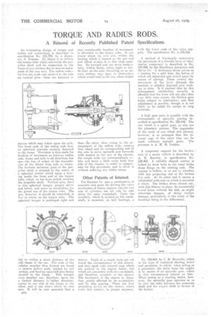
An interesting design of torque and radius rod connections is described in specification No. 121,724, by a Japanese; S. Tamura. Its object is to relieve the torque tube which surroundsthe propeller shaft and its :connection to the frame of any stresse.s due to uneven movement of the rear axle. The radios rods-for two are uzed—are secured to the axle on vertical pins: these are fastened to slee es which may rotate upon the axle. The front ends of the radius rods bear on spherical journals securely fastened to the frame. Provision is thus made for freedom of movement as between radius rods, frame and axle in all directions but one—the line of action of the transimisniorl of the thrust from axle to frame. The forward universal joint of the propeller shaft is situated in the centre of a spherical carrier which takes a bearing inside the front end of the torque tube, which, as has been stated, encloses the propeller shaft. Vertical pins, fixed to this spherical hanger, project above and below, and serve as connections for the jawed end of the torque tube. The jaw, however, it should be remarked, is free to rotate on the torque tube. The spherical hanger is prolonged right and left to within a short distance of the side frame of the car. The ends of the Lobular member thus formed are bored to receive hollow pads, backed by coil springs, and bearing upon hali pins firmly secured to the frame. This tubular cross member can, therefore, move for a limited distance ieeither direction, nearer to one side of the frame or the other, and it can wotate about its own axis. It will be now apparent Ihat a .1351
very considerable freedom Of movement is allowable to the torque tube.. 'It can rotate about its own axis within the bearing which is formed on the jaw end and which secures it to this cross:member. Its forward •end can move horizontally, within limits, either right or left. So that, as the axle, travelling Onan -Uneven surface, mile, Meet an obstruction which would tend to lift one wheel higher than tte other, thus, owing to the arrangement of the radius rods, causing that wheel and its corresponding end of the axle to move upwards and forwards with respect to the rest of the .chassis, the torque tube can correspondingly rotate and move a little away from that side of the chassis, in order to compensate for this movement, and to allow it without suffering any undue stress.
Other Patents of Interest.
The Daimler Co. uses a combination of eccentric and gears for driving the valve mechanism of rotary engines wherein two sets of cylinder* are set side by side along the same crankshaft. Upon the eccentric, which is secured to the crankshaft, is mounted, on ball: bearings; a sheave. Teeth of a simple form are cut round the circumference of this sheave, and they mesh with internal cogs which are secured to the engine frame; but which are concentric with the crankshaft, and therefore, eccentric to the sheave. The Movement of the sheave is, therefore, jointly affected by its eccentricity and by this gearing. There are four projecting perizs on the sheave, which come into contact, in proper sequence, with the lime! ends of the valve tappets. The .specification No. is.129,352.
A method of frictionally restraining the movement of a throttle lever or other similar component is described in No. 129,436; by the Blackburn Aeroplane and Motor' Co. -A stationary' drum serves as a 'bearing for a split boss, the halves of which are separated and prised apart by means of' Springs. These control the movement of the lever through the medium of suitably disposed pins working in slots. It is claimedthat by this arrangement satisfactory security is afforded that the lever will not slip ; that very little wear occurs, the friction gear being subject to lubrication ; and that adjustment is possible, though it is not likely to be called for except at long intervals.
A high gear ratio is possible with the arrangement of epicyclic gearing de, scribed In specification No. 129,446. The sun wheel is a spiral gear, as also are the planetary pinions. The angularity of the teeth of sun wheel and pinions, however,' is so arranged • that the internal cogs of the outer ring can be made ordinary straight gears. The patentee is A. H. R. Feaden. 1 A temporary support for the broken axle of a motor vehicle is described by A. E. Bentley, in specification No. 129,462. A suitably shaped casting is bolted by hook bolts to the usual brake drum flange on the existing axle. The casting is hollow, so as not to interfere with any projecting end of the broken live axle. At, its outer end it carries a substantial stub axle on which is mounted a wheel. The broken down chassis can, with this fitment in place, be successfully towed home without the risk, as might otherwise happen, of doing further damage, particularly in the event of the breaka,Ye being in the differential.
No. 129,463, by C. H. Reynolds, refers to the type of combined starting motor and generator, in whith when acting as a-generator, the drive from the engine is by means of an epicyclic gear, which in this circumstance rotates en bloc. When acting-as a starting motor, how-ever, the epicyclic gear operates so as to vary the ratio between the armature shaft and the engine shaft in favour oi the former.