 1
1 2
2 3
3 4
4 5
5 6
6 7
7 8
8 9
9 10
10 11
11 12
12 13
13 14
14 15
15 16
16 17
17 18
18 19
19 20
20 21
21 22
22 23
23 24
24 25
25 26
26 27
27 28
28 29
29 30
30 31
31 32
32 33
33 34
34 35
35 36
36 37
37 38
38 39
39 40
40 41
41 42
42 43
43 44
44 45
45 46
46 47
47 48
48 49
49 50
50 51
51 52
52 53
53 54
54 55
55 56
56 57
57 58
58 59
59 60
60 61
61 62
62 63
63 64
64 65
65 66
66 67
67 68
68 69
69 70
70 71
71 72
72 73
73 74
74 75
75 76
76 77
77 78
78 79
79 80
80 81
81 82
82 83
83 84
84 85
85 86
86 87
87 88
88 89
89 90
90 91
91 92
92 93
93 94
94 95
95 96
96 97
97 98
98 99
99 100
100 101
101 102
102 103
103 104
104 105
105 106
106 107
107 108
108 109
109 110
110 111
111 112
112 113
113 114
114 115
115 116
116 117
117 118
118 119
119 120
120 121
121 122
122 123
123 124
124 125
125 126
126 127
127 128
128 129
129 130
130 131
131 132
132 133
133 134
134 135
135 136
136 137
137 138
138 139
139 140
140 141
141 142
142 143
143 144
144 145
145 146
146 147
147 148
148 149
149 150
150 151
151 152
152 153
153 154
154 155
155 156
156 157
157 158
158 159
159 160
160 161
161 162
162 163
163 164
164 165
165 166
166 167
167 168
168 169
169 170
170 171
171 172
172 173
173 174
174 175
175 176
176 177
177 178
178 179
179 180
180 181
181 182
182 183
183 184
184 185
185 186
186 187
187 188
188 189
189 190
190 191
191 192
192 193
193 194
194 195
195 196
196 197
197 198
198 199
199 200
200 201
201 202
202 203
203 204
204 205
205 206
206 207
207 208
208 209
209 210
210 211
211 212
212 213
213 214
214 215
215 216
216 217
217 218
218 219
219 220
220 221
221 222
222 223
223 224
224 225
225 226
226 227
227 228
228 229
229 230
230 231
231 232
232 233
233 234
234 235
235 236
236 237
237 238
238 239
239 240
240 241
241 242
242 243
243 244
244 245
245 246
246 247
247 248
248 249
249 250
250 251
251 252
252 253
253 254
254 255
255 256
256 257
257 258
258 259
259 260
260 261
261 262
262 263
263 264
264 265
265 266
266 267
267 268
268 269
269 270
270 271
271 272
272 273
273 274
274 275
275 276
276 277
277 278
278 279
279 280
280 281
281 282
282 283
283 284
284 285
285 286
286 287
287 288
288 289
289 290
290 291
291 292
292 293
293 294
294 295
295 296
296 297
297 298
298 299
299 300
300 301
301 302
302 303
303 304
304 305
305 306
306 307
307 308
308 309
309 310
310 311
311 312
312 313
313 314
314 315
315 316
316 317
317 318
318 319
319 320
320 321
321 322
322 323
323 324
324 325
325 326
326 327
327 328
328 329
329 330
330 331
331 332
332 333
333 334
334 335
335 336
336 337
337 338
338 339
339 340
340 341
341 342
342 343
343 344
344 345
345 346
346 347
347 348
348 349
349 350
350 351
351 352
352 353
353 354
354 355
355 356
356 357
357 358
358 359
359 360
360 361
361 362
362 363
363 364
364 365
365 366
366 367
367 368
368 369
369 370
370 371
371 372
372 373
373 374
374 375
375 376
376 377
377 378
378 379
379 380
380 381
381 382
382 383
383 384
384 385
385 386
386 387
387 388
388 389
389 390
390 FUTURE COMMERCIAL VEHICLE BRAKING REQUIREMENTS
Page 228
Page 245
Page 246
Page 247
Page 248
Page 253
Page 254
If you've noticed an error in this article please click here to report it so we can fix it.
The fourth paper presented to "The Commercial Motor" Fleet Management Conference
1N THIS paper I am attempting to survey the desirable
lines ,of development of commercial vehicle braking from the user's point of view, as distinct from suggesting new regulations. It will probably be necessary for the Minister to make regulations to bring this country into line with other European countries, but the standards being discussed at present may need modification as traffic conditions alter and new technical developments take place. Therefore I wish to exclude any discussions of regulations from this paper and concentrate entirely on the design targets which our manufacturers should set out to achieve in their production vehicles during the next few years. Buses are treated as being commercial vehicles for the purposes of this paper.
064
FEATURES RELATED TO BRAKING
Springing
BEFORE considering brakes proper, there is one obvious
fact which is worth some consideration and that is that a vehicle's tyres can only develop a retarding force from their grip on the road when they are actually in contact with the road. Yet it is a common thing to see the rear wheels of an unladen goods vehicle bouncing clear of the road surface even when travelling on good surfaces which only have very minor bumps.
Therefore it is important that suspension systems are evolved which have much wide ranges of spring rates and spring damping, so that they are equally effective under all loading conditions. With the vehicle fully laden the springs and their damping must be firm enough to maintain stability. In the unladen condition they must be soft enough to keep the wheels firmly in contact with the road.
When a wheel bounces off the road surface while the brakes are applied, it slows down very rapidly and therefore some skidding occurs when the tyre makes contact with the road again. This can result in the wheel remaining locked as the skidding tyre will have less grip on the road than a rolling tyre would. It has been shown that, over a wide range of road surface and tyre tread combinations, the maximum grip is obtained with the wheel still rolling and the grip falls to about one half of this value when the wheel is locked.
This large reduction in the grip available for braking is accompanied by the almost total disappearance of the ability of the tyre to exert a sideways force, which means that a locked wheel cannot play its proper part in maintaining directional control of the vehicle. As it is most important to retain directional control whilst braking, I will assume that the limit of performance of a vehicle's brakes has been passed when the first wheel locks. This conception has an important bearing on some of the later considerations.
Security of Load WE NORMALLY refer to the brakes as something used
to bring the vehicle to a halt, but we must also think of them as bringing the vehicle's load to a halt; and the load often weighs twice as much as the unladen vehicle. This means that two-thirds of the braking force developed by the tyres' grip on the road may have to be transmitted as a horizontal force from the vehicle to its load. If we take the case of a vehicle weighing 26,000 lb. laden, which is carrying a load of 17,500 lb., and examine the forces developed to stop it with a deceleration of 0.5g, we find that the total grip of the tyres on the road must be 13,000 lb. and a force of 8,750 lb. must be developed between the vehicle and its load.
This force is nearly 4 tons, and it is extremely unlikely that it can be produced by the friction between the load and the floor of the vehicle. This means that headboards and lashing points of adequate strength must be provided, and that everyone who has a responsibility for a loaded vehicle must be educated in the proper ways to place the Load on a vehicle and to secure it against -the forces leveloped while it is in motion—especially during braking, 3ornering and acceleration.
SERVICE BRAKES
Deceleration Standard PROBABLY the easiest thing to specify about the L required performance of the service brake (that is the wake normally used to control the speed of the moving /allele), is the retardation to be achieved on a flat road vith a good surface when the vehicle is loaded up to its naximum design weight with uniformly distributed test veights, and I am going to suggest that a figure of 0.5g hould be attained. This is the minimum figure in use Low for cars and goods vehicles up to 30 cwt. unladen .nd it is quite common for cars to go up to close on 1-0g iut such high decelerations are not desirable in a commerial vehicle as it becomes so difficult to retain the load be it goods or passengers in the case of buses) in position. 7o avoid such high decelerations when lightly loaded, it would be very advantageous to have brakes which could always achieve 0.5g hut which did not greatly exceed 0.5g under any condition.
Distribution between Axles WITH existing designs and techniques there does not " appear to be any great difficulty in achieving this figure of 0-5g in the fully laden condition on a good road surface (say with a coefficient of friction of 0.7 or better); but the present systems which have a fixed distribution of braking between axles can be very inefficient under other conditions, especially when we bear in mind the criterion that no wheel must lock. Out of the vast range of conditions of loading, deceleration and road surface it is instructive to consider slippery road conditions when the coefficient of friction between tyre and road is, say 0.2.
If we have a distribution of braking which is perfectly suited to the particular loading conditions (including weight transference), it is possible to achieve a vehicle deceleration of 0-2g; but if there is a fixed distribution it is possible that locking of the wheels on one axle will occur when the deceleration has only reached 0-1g.
As this locking of the wheels on one axle will generally cause loss of directional control, it means that the driver should not try to get more braking; but he will probably be tempted to apply the brakes harder in the hope that he will stop quicker, in spite of the loss of control. He will not be successful because the skidding wheels have lost half of the grip that they had when they were still rolling. The increased braking effort that the harder application of the brakes causes in the other axle (or axles) is unlikely to make up for this loss of grip of the skidding wheels.
This loss of performance from a potential 0-2g to 0-1g is very serious, as the following figures show. If we forget about driver reaction time and system response time, and consider 20 m.p,h. as a likely speed on slippery roads, we find that the braking distance for 0.2g is 66 ft., which is already too long for safety; but it only 0.1g can be obtained then the braking distance goes up to 132 ft. This large increase of the braking distance under poor road conditions is a very high price to pay for the cheaper cost and greater simplicity of a braking system which has a fixed distribution between axles.
And-locking Systems A S a limiting factor is wheel locking it is tempting to
think of anti-wheel locking systems as an immediate solution to the problem. The basic idea of these systems is to have a small flywheel driven from the road wheel via suitable gearing; but so arranged that if the road wheel slows up more quickly than it can do during normal braking (i.e. it is about to lock), then the drive to the fly
wheel is disconnected. This disconnection is made to operate a valve which releases the brake on that road wheel, which then ceases to slide on the road and restores rolling friction between the tyre and the road. When this has happened the brake is re-applied and the cycle is repeated. Thus the tyre is constantly maintained very close to the conditions which give the maximum grip possible on that particular road surface.
As the individual brakes are repeatedly released and re-applied while the driver's foot is maintaining a steady pressure on the pedal, it is essential to have power assistance available.
Anti-locking systems can produce a considerable improvement but it is unfair for them to be regarded as the cure for all braking problems. A sounder approach is to have a system which automatically adjusts the proportion of braking on each axle to its load. Then anti-lock devices could be incorporated under conditions where they will be given the chance to develop their full advantages.
Braking Adjusted to suit Load VARIATIONS of loading conditions not only alter the v desirable distribution of braking between axles but they also alter the pedal pressure which the driver must exert for any given value of deceleration. This can show up badly under two extreme (but often met with) conditions in that the pedal pressure may be excessively high when fully loaded or it may be too light for sensitive braking when running lightly loaded on slippery roads.
A Possible System
m
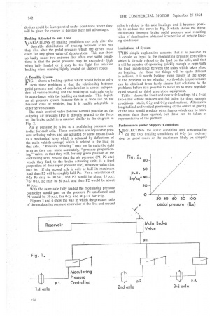
r. 1 shows a braking system which would help to solve
both these problems in that the relationship between pedal pressure and value of deceleration is almost independent of vehicle loading and the braking at each axle varies in accordance with the loading on that axle. This depicts an air pressure system because this is in wide use on the heaviest class of vehicles, but it is readily adaptable to other servo-systems.
The main control valve follows normal practice as the outgoing air pressure (Pc) is directly related to the force on the brake pedal in a manner similar to the diagram in Fig. 2.
Air at pressure Pc is led to a modulating pressure controller for each axle. These controllers are adjustable pressure reducing valves and are adjusted by some means (such as a mechanical lever which is actuated by deflections of the main vehicle springs) which is related to the load on that axle. "Pressure reducing" may not be quite the right term as they are, more accurately, "pressure proportioning" valves in that they will, for any given position of the controlling arm, ensure that the air pressure (P1, P2 etc.) which they feed to the brake actuating units is a fixed proportion of their input pressure (Pc), whatever value that may be. If the second axle is only at half its maximum load then P2 will be roughly half Pc. For a retardation of 0-2g Pc may be 30 p.s.i. and P2 would be about 15 p.s.i. ror 0-5g, Pc may be 80 p.s.i. and then P2 would be about 40 p.s.i.
With the same axle fully loaded the modulating pressure controller would pass on the pressure Pc unaffected and P2 would be 30 p.s.i. for 0-2g and 80 p.s.i. for 0-5g.
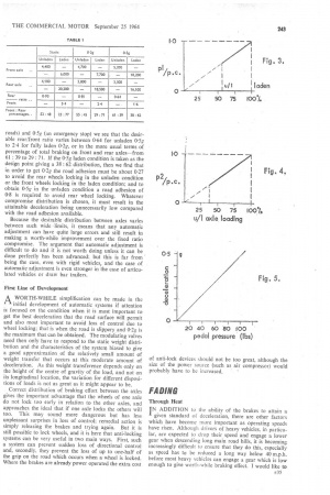
Figures 3 and 4 show the way in which the pressure ratio of the modulating pressure controller of the first and second axles is related to the axle loadings, and it becomes possible to deduce the curve in Fig. 5 which shows the direct relationship between brake pedal pressure and resulting value of deceleration obtained irrespective of vehicle loading conditions.
Limitations of System THIS simple explanation assumes that it is possible to I obtain an input to the modulating pressure controllers which is directly related to the load on the axle, and that it will be capable of operating quickly enough to cope with the load transference between the axles which takes place on braking. As these two things will be quite difficult to achieve, it is worth looking more closely at the scope of the problem to see whether worth-while improvements can be obtained from fairly simple first solutions to the problems before it is possible to move on to more sophisticated second or third generation equipment.
Table I shows the front and rear axle loadings of a 7-ton two-axled vehicle unladen and full laden for three separate conditions—static, 0-2g and 0-5g decelerations. Alternative longitudinal and vertical positioning of the centre of gravity of the load would produce other figures which can be more extreme than those quoted, but these can be taken as representative of the problem.
Performance under Slippery Conditions MEGLECTING the static condition and concentrating .41 on the two braking conditions of 0-2g (an ordinary stop on good roads or the maximum likely on slippery
roads) and 0.5g (an emergency stop) we see that the desirable rear/front ratio varies between 0-64 for unladen 0.5g to 14 for fully laden 0.2g, or in the more usual terms of percentage of total braking on front and rear axles—from 61: 39 to 29 : 71. If the 0-5g laden condition is taken as the design point giving a 38 : 62 distribution, then we find that in order to get 0.22 the road adhesion must be about 0.27 to avoid the rear wheels locking in the unladen condition or the front wheels locking in the laden condition; and to obtain 0-5g in the unladen condition a road adhesion of 0.8 is required to avoid rear wheel locking. Whatever compromise distribution is chosen, it must result in the attainable deceleration being unnecessarily low compared with the road adhesion available.
Because the desirable distribution between axles varies between such wide -limits, it means that any automatic adjustment can have quite large errors and still result in making a worth-while improvement over the fixed ratio compromise. The argument that automatic adjustment is difficult to do and it is not worth doing unless it can be done perfectly has been advanced; but this is far from being the case, even with rigid vehicles, and the case of automatic adjustment is even stronger in the case of articulated vehicles or draw bar trailers.
First Line of Development AWORTH-WHILE simplification can be made in the initial development of automatic systems if attention is focused on the condition when it is most important to get the best deceleration that the road surface will permit and also most important to avoid loss of control due to wheel locking; that is when the road is slippery and 0.2g is the maximum that can be obtained. The modulating valves need then only have to respond to the static weight distribution and the characteristics of the system biased to give a good approximation of the relatively small amount of weight transfer that occurs at this moderate amount of deceleration. As this weight transference depends only on the height of the centre of gravity of the load, and not on its longitudinal location, the variation for different dispositions of loads is not as great as it might appear to be.
Correct distribution of braking effort between the axles gives the important advantage that the wheels of one axle do not lock too early in relation to the other axles, and approaches the ideal that if one axle locks the others will too. This may sound more dangerous but has less unpleasant surprises in loss of control; remedial action is simply releasing the brakes and trying again. But it is still possible to lock wheels, and it is here that anti-locking systems can be very useful in two main ways. First, such a system can prevent sudden loss of directional control and, secondly, they prevent the loss of up to one-half of the grip on the road which occurs when a wheel is locked. Where the brakes are already power operated the extra cost of anti-lock devices should not be too great, although the size of the power source (such as air compressor) would probably have to be increased, '
FADING
Through Heat IN ADDITION to the ability of the brakes to attain a given standard of deceleration, there are other factors which have become more important as operating speeds have risen. Although drivers of heavy vehicles, in particular, are expected to drop their speed and engage a lower gear when descending long main road hills, it is becoming increasingly difficult to ensure that they do this, especially as speed has to be reduced a long way below 40 m.p.h. before most heavy vehicles can engage a gear which is low enough to give worth-while braking effect. I would like to
suggest that it should be possible for a fully laden vehicle to descend a hill of average gradient of 1 in 10 for 1+ miles in top gear at a steady speed of 40 m.p.h. and to be able to bring the vehicle to a halt at the end of the hill with a retardation at least equal to 80 per cent of the performance of a cold brake.
When talking of brake fade, it is no use quoting a point at which the brakes have already lost an appreciable part of their stopping powers while the vehicle is still moving. The only figure of interest is the amount of energy that the brakes can absorb and still retain the ability to bring the vehicle to a complete standstill with adequate deceleration.
" Fade " is not only caused by the rising temperature of the brake linings. It is very frequently caused by inability to keep the linings in contact with the drums as the latter expand with the heat. The range of movement of the centre of the shoe has been taken as about 0.08 in. for a 15 in. diameter drum, but this is now considered inadequate, by some designers and as hopelessly inadequate 1:ry others. Figures of over 0.2 in. are in use on some vehicles.
As it is essential to allow both for some lining wear since. the last adjustment, and for the drum expansion, there seems to be a strong case for being generous with the travel available. It would be better if brakes could be cooled so well that high temperatures of drums and linings could be avoided; but there seems little likelihood that brakes can be produced within the next ten years which do not depend very largely on the thermal capacity of the drums to limit the upper temperature reached in a maximum deceleration stop from top speed, and therefore this problem of drum expansion will stay with us.
Even brake units which are self adjusting for clearance are not as attractive as they appear to be at first sight in reducing the need for large movement of the shoes, as it is possible for the adjustment to compensate for the drum expansion lo such an extent that, after the brake has been released arid the drums start to cool, they can contract until they are rubbing the linings. As the brake is in the off position, the driver can do nothing to free the brakes again. If this problem can be avoided, it would be very desirable to have self-adjusting brakes.
When a brake unit is heated, the best known effects are that first of all the rate of wear of the linings increases rapidly and then their coefficient of friction can fall to a very low figure and thus cause " fade ". But this is not the only effect, as heating of the brake-operating mechanism can also be of importance, especially when an operating cylinder is fastened to the brake back plate. The specification of hydraulic fluid has had to be improved in recent years to take account of this, and further improvements may be necessary during the next decade.
Through Speed A T HIGH rubbing speeds it is possible for the frictional
properties of a lining to fail and, although this effect is not prevalent, it is serious-and alarming when it does occur. If the initial deceleration is lower than expected, then the vehicle travels for a longer period of time at high speed and this increases the stopping distance considerably more than the increase of speed would otherwise cause. Most other features of brake performance can be predicted from tests carried out at speeds which are well below the vehicle's maximum. But to check on this possible defect there is no substitute for a brake test carried out at the vehicle's maximum speed.
EMERGENCY BRAKES
Requirements DURING the design of a braking system, it is essential to consider what the effect would be of a failure of E36
any single part of it. With the high density of traffic on our roads, the ability of a driver to "steer out of difficulty" has almost disappeared and a considerable improvement is needed in the performance of the emergency braking systems—especially of the heavier goods vehicles.
It has been conventional to accept that it is adequate to have half the normal deceleration available after any single failure has occurred in the service brake. This appears to be acceptable to someone who is concerned with overcoming the design difficulties at reasonable expense; but safety considerations demand that much more -than that ought to be provided. Many failures may only become apparent to the driver when he applies the brake; there is then an inevitable time lag before he can react to the situation and apply an alternative brake.
The reference to applying an alternative brake is based on the thought that the ideal method of making sure that a failure in the service brake is not disastrous is to have a separate braking system with its own control, transmis sion and brake units. This is rarely possible, largely because of the difficulty of providing another set of drums or discs; the provision of a separate control and transnriission does not pose any particularly difficult problem but, if the same brake units are used, they must have adequate capacity to avoid fading due to overheating.
The time lost while the driver reacts to a brake failure and then operates another control can be eliminated if the foot brake pedal operates a divided system which is still capable of giving the emergency brake performance after failure of the normal service brake.
Fade .Resistance IN ADDITION to providing good deceleration, the emer
gency braking system has its own fading problems when it does not apply brakes on all axles. It needs to be able to bring the vehicle to a complete standstill with adequate deceleration under all conditions—such as when the driver applies the foot brake at the top of a hill and finds that it has failed. The brakes are already warm, or even hot, from normal driving and the speed is too high (say 40 m.p.h.) for it to be possible to engage a lower gear. He should, of course, have changed down before starting the descent, but the start of the hill is often quite gradual and it is very tempting to delay reducing speed until the down gradient is appreciable.
A brake failure at this point throws the whole burden of stopping on to the emergency brake because the vehicle's speed is too high. The emergency brake has a hard job dissipating not only the kinetic energy of the vehicle but also a considerable amount of potential energy as it will, in many cases, be descending the steepest part of the hill before it stops. This standard of performance is likely to be very difficult to meet if the emergency brake only works on one axle and this, together with the need to give a degree of deceleration which is more than half of the service brake's capabilities, makes a very strong case for having an alternative means of operating all brakes on all axles.
A further reason in favour of this proposal is that it is difficult to get enough deceleration out of, for example, only the rear axle of an unladen two-axle vehicle without a real danger of locking the rear wheels and hence losing directional control.
Divided Systems A N ALTERNATIVE scheme to having a separate control and transmission for the emergency brake is tc have a divided system so arranged that a single failure will not make the whole service brake inoperative. This can be a good idea, but it does need to be something more than just a dual master cylinder or dual pedal valve if any worth-while amount of emergency braking is to be guaranteed.
The previously advanced needs to retain braking on all axles still apply, and this is not provided by a simple divided system. Furthermore, the braking effort will rarely be divided equally between axles. Because of that, it is possible for a failure to occur on the less heavily braked axle without it being readily apparent to the driver until he wants to use the full stopping power of the brakes— which may not be for quite a long time. The pedal travel may be more than usual but pedal pressures may well be normal. The driver then thinks that he still has the safety of the divided system whereas he is, in fact, relying on a single system which only works half of the main system.
Warning of First Failure IF A divided system is to count as both the service brake, I and the emergency brake, it is essential that the driver is warned when the first failure has occurred so that he will know that the failure must be corrected immediately. In the case of hydraulic systems, this warning must be more comprehensive than warnings of low fluid levels in the reservoirs, as it must give warning of faulty cup washers in master cylinders or brake units and also pipeline failures.
This means that it should be operated by the pressures that are in the pipeline when the brake is operated, and give a warning which persists after the brake is released whenever the pressures in the two parts of the system are not the same. In air pressure and vacuum systems the pressures in the storage tanks can be displayed on gauges, and other warnings can be operated whenever the reserve of servo energy -drops below a predetermined value.
PARKING BRAKES
Requirements I N SOME cases the parking brake and emergency brake may be the same, or at least operated by the same control, but in other cases they will be separate systems and this section deals only with the purely parking performance. There is no need, for example, for a parking brake to have any particular anti-fade properties because no heat is generated in a brake while it is holding a vehicle stationary.
If, however, the brake units used for the parking brake are the same as those used for the service or emergency brakes, then it is essential that there is adequate capacity to hold the vehicle on a gradient when the brakes are hot. When the vehicle is parked with hot brakes, it must not be possible for the brake to become less effective as the brake cools down as this may let the vehicle move; nor, on the other hand, must contraction of the drums cause the brake to lock on to such an extent that it causes damage to the drums or it cannot be released.
The parking brake should be able to hold the vehicle stationary on a gradient of 1 in 4 when facing either uphill or downhill at any loading condition. Because of the low weight on some axles in the unladen condition, it may often be necessary for the brake to work on more than one axle to ensure that the braked wheels have enough road adhesion between them.
It is becoming increasingly difficult, especially on articu lated vehicles, to provide a parking brake which is applied through completely mechanical linkages; but the principle that a parking brake must be held on by purely mechanical devices without servo-assistance is a sound principle which we should not contemplate forsaking.
One promising way is to use mechanical energy stored in one or more springs to apply the brake and air pressure (or other servo medium), which is used to operate the service brake to release the parking brake. Such a system has also the very worth-while advantage that the vehicle cannot be moved until the service braking system is properly supplied with power. This advantage becomes increasingly important if the air compressor (or equivalent) is overdue for replacement, and it takes so long to charge the reservoir that the driver is tempted to take the vehicle on the road with inadequate brakes.
TANDEM AXLES
BEFORE moving on to deal with the special problems posed by articulated vehicles, 1 would like to mention the need to regard the suspension system as part of the braking system. Early in the paper there was reference to the need to have springs of variable rate, with suitable damping, to ensure that the loadings between the wheels and the road do not vary through too wide a range—at least when travelling on normal road surfaces—and, in particular, that lightly loaded wheels should not bounce clear of the road.
When the brakes are applied heavily the torque developed in each brake is developed equally on the stationary members of the brake and these must be counteracted. On single axles it is often tolerable if the spring members themselves are used to resist the braking torque; but this can be horribly inadequate with tandem axles, especially when there is some deliberate coupling of the suspensions of the two axles with the object of controlling the distribution of loads between them. In these cases it is imperative that brake torque is catered for by means which relieve the spring members of any appreciable amount of spring "wind up ". The responsibility for this must rest entirely with the vehicle designer as it embraces the activities of more than one component supplier.
ARTICULATED VEHICLES
FROM a braking point of view, articulated vehicles pose four problems which are not met with in rigid vehicles; and two problems are posed to a more severe degree than they are in rigid vehicles.
Relationship between Tractor and Semi-trailer Brakes THE problem of getting proper braking distribution between all the axles of an articulated vehicle is made more difficult by the fact that most tractor units are made by firms that do not make any semi-trailers and most semi-trailers are made by firms who do not make tractor units. Yet each manufacturer can only design -his product properly if he knows precisely how the braking system of the units to which it may be coupled are designed. As one of the main attractions of articulated vehicles is the ability of any tractor to operate with a number of semitrailers (and vice versa), it seems to be essential to establish a design standard centred on the coupling device. In the case. of an air pressure system, for example, the need is to define: the limits between which the air pressure is to be maintained in the reservoirs; the pressure in the actuators on each axle which is to be assumed when the fully laden vehicle is being braked at, say, 0.5g; the way r41 in which air pressure and deceleration are to be related to each other for other values; the mechanical details of the coupling; whether the half coupling is to be mounted on the vehicle directly or at the end of a flexible connection; and the maximum time delay in operation.
It is not only the service brake which is concerned, of course, because similar information is needed for the emergency and parking brake systems.
Jack-knifing
WHEN a two-axled tractor coupled to a single-axled " semi-trailer is travelling' on a normal road (i.e. with a small amount of camber), and the brakes are applied so that the wheels of either axle on the tractor are locked, it will jack-knife. The speed with which this happens will be highest when the tractor driving wheels are locked.
If the wheels of the semi-trailer axle are locked, the back of the vehicle will swing around in an uncontrolled manner, which is dangerous even though it is not as violent as a jack-knife.
The earlier comments on the need to apportion braking effort correctly between the axles apply with even greater force to articulated vehicles than they do to rigid vehicles, because the effect of locking wheels is worse. Once the wheels of one axle have been locked, the subsequent jackknifing develops more quickly when the roads are dry than when they are slippery because the disturbing forces are higher; but recovery can also be more certain provided the driver takes immediate action—mainly releasing the brakes. Really quick appreciation of the situation and corrective action by the driver is essential as, otherwise, the two parts of the vehicle soon get to a relative position from which recovery is impossible.
But in spite of thejack-knifing being more sudden and apparently, therefore, more dangerous at decelerations of 0.5g and over, I think that in cases where full proportioning of axle braking to axle load is not provided, the braking distribution should be chosen to have the smallest error as about 0-2g—that is to ensure that at times when the road is slippery and stopping distances are perforce lengthened the vehicle is able to make the best use of what road grip is available.
Anti-wheel locking devices appear to be of such enormous value on articulated vehicles that I hope the next 10 years will see every vehicle equipped at least on the driving axle. In referring to "at least on the driving axle" I have in mind that it should be possible to modify existing vehicles to that extent; but new vehicles ought also to apply this feature to the trailer axle in all cases, and preferably the front axle of the tractor as well.
Trailer Breakaway THE third aspect in which articulated vehicles have A features entirely different from rigid vehicles is the possibility of the coupling between the two parts breaking. There is no difficulty in arranging that the braking system of the tractor will be left in a safe working condition so that the driver can have normal control of it. But the trailer will have neither a full set of wheels nor a driver, and it must therefore be brought to a standstill as soon as possible by automatic application of its own brakes.
Separate Reservoirs
THE brakes on all the axles of a rigid vehicle can be operated from the same reservoir of energy; but the axle (or axles) of a semi-trailer must always have their own reservoir in order to operate the brakes if the semitrailer breaks away from the tractor. This reservoir of its own is also useful in reducing the delay time in normal brake operation.
E42 The preceding four items are not applicable to rigid vehicles (unless they are used with a drawbar trailer), but the following two items are only different in degree between rigid and articulated.
Laden/Unladen Ratio
THE impossibility of choosing a fixed distribution of braking effort between axles which is a satisfactory compromise is even more apparent in the case of trailer axles than it is with rigid vehicles. The trailer axle can always be lighter than a driven axle, and therefore the ratio of maximum laden weight to unladen weight can always be greater. The previously advanced view that suspensions must be improved in the range over which their rate can vary to suit the load, and that braking effort must also vary in sympathy with the axle load, are applicable with greater force to trailer axles.
Time Delay
BECAUSE the rear axle of a semi-trailer can be appreciably farther away from the driver's control, it means that it is more difficult to keep the time delay in operation of its brakes within acceptable limits. A great deal of emphasis is sometimes laid upon the necessity for the trailer axle brakes to be applied first and for the tractor rear and front axle brakes to follow in that order. This is certainly true if the intervals between them are of the order of a few seconds. But if the time delay at the farthest axle is kept below about 0-4 seconds, it is unlikely that there will be any point in trying to control the order in which they come on—the distribution between axles when they are all applied is of much greater importance.
CONCLUSION
SSOME of the heavier vehicles which will be built in 10 years' time will probably still be on the roads in 30 years from now, when traffic conditions will be very different. Consequently it will not be enough to think of brakes which are a slight improvement on some of the older vehicles that are on the roads today. We must accept that some of the increased productivity of the larger, faster vehicles must be "ploughed back" into the vehicles themselves and that more money must be devoted to providing braking system which are an advance on today's designs.