


Tipping Gear with New Features
Page 53
If you've noticed an error in this article please click here to report it so we can fix it.
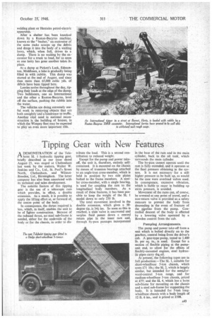
A DEMONSTRATION of the Teler't hoist SL 1 hydraulic tipping gear, briefly described in our issue dated August23, was staged at Cheltenham last week by the makers, Walter W. Jenkins and Co., Ltd., St. Paul's Street North, Cheltenham, and WilmotBreeden, Ltd., Birmingham. The latter company has also been associated with its technical and sales development.
The notable feature of this tipping gear is the use of a telescopic ram which provides, in effect, a double extension. As a result, it is possible to apply the lifting effort at, or forward of,, the centre point of the body.
In consequence, the thrust required is less, which, in itself, enables the unit to be of fighter construction. Because of the reduced thrust, no steel sub-frame is needed, either for the underside of the body or for the chassis, in order to dis tribute the load. This is a second contribution to reduced weight.
Except for the pump and power takeoff, the unit is, therefore, entirely selfcontained. It is mounted on the chassis by means of trunnion bearings attached to an angle-iron cross-member, which is held in position by two side plates bolted to the frame members. A similar cross-member, with a single bearing, is used for coupling the ram to the longitudinal body members. As a result of these features, it has been possible to keep the weight of the SL 1 model down to only 250 lb.
The total movement involved in the double extension, which gives a 50degree tip, is 344 ins. So soon as this is reached, a slide valve is uncovered and surplus fluid passes down a central return pipe in the inner ram and, through by-pass passages incorporated in the base of the ram and in the main cylinder, back to the oil tank, which surrounds the main cylinder.
The by-pass cannot operate until the ram is fully extended, and it operates at the final pressure obtaining in the system. It is not necessary for a still higher pressure to be built up, as would be the case were overload valves used. In consequence, excessive vibration. which is liable to occur in building up extra pressure, is avoided.
Movement of the rams can, of course. be arrested at any point of travel, and a non-return valve is provided as a safety measure to prevent the body from descending in the event of fracture of the pjpeline from the pump. Controlled descent of the body is effected by a lowering valve operated by a Bowden control from the cab.
Pumping Arrangements.
The pump and power take-off form a unit which is bolted directly on to the gearbox, control being from the driver's cab. A gear-type pump, tested to 1,400 lb. per sq. in., is used. Except for a section of flexible piping at the pumpunit end, to allow for the effects of flexibly-mounted engines, steel hydraulic pipes carry the, oil.
At present, the following types are in full production:—The SL 1, suitable for short-wheelbase 5-ton chassis, which costs £71 10s.; the SL 2, which is largely similar, but intended for the semi:forward-control 5-ton range, and for medium-wheelbase 5-ton chassis, priced at £77; and the SL 4, which has a hoist sub-frame for mounting on the chassis and a steel sub-frame for supporting the body. It is intended for 5-ton longwheelbase chassis with a body length of 12 ft. 6 ins., and is priced at £108.