 1
1 2
2 3
3 4
4 5
5 6
6 7
7 8
8 9
9 10
10 11
11 12
12 13
13 14
14 15
15 16
16 17
17 18
18 19
19 20
20 21
21 22
22 23
23 24
24 25
25 26
26 27
27 28
28 29
29 30
30 31
31 32
32 33
33 34
34 35
35 36
36 37
37 38
38 39
39 40
40 41
41 42
42 43
43 44
44 45
45 46
46 47
47 48
48 49
49 50
50 51
51 52
52 53
53 54
54 55
55 56
56 57
57 58
58 59
59 60
60 61
61 62
62 63
63 64
64 65
65 66
66 67
67 68
68 69
69 70
70 71
71 72
72 73
73 74
74 75
75 76
76 77
77 78
78 79
79 80
80 81
81 82
82 83
83 84
84 85
85 86
86 87
87 88
88 89
89 90
90 91
91 92
92 93
93 94
94 95
95 96
96 97
97 98
98 99
99 100
100 101
101 102
102 103
103 104
104 105
105 106
106 107
107 108
108 109
109 110
110 111
111 112
112 113
113 114
114 115
115 116
116 117
117 118
118 119
119 120
120 121
121 122
122 123
123 124
124 125
125 126
126 127
127 128
128 129
129 130
130 131
131 132
132 133
133 134
134 135
135 136
136 137
137 138
138 139
139 140
140 141
141 142
142 143
143 144
144 Important
Page 81
Page 82
Page 83
If you've noticed an error in this article please click here to report it so we can fix it.
Crossley Developments An Entirely New Trolleybus Chassis Now in Production, Together With an. Automatic Self-selecting and Self-changing Four-speed Gearbox ALTHOUGH the range of oil and petrol-engined passenger and goods chassis, which has, in the past, formed the main part of the programme of Crossley Motors, Ltd., Gorton, Manchester, is continued for the new season, there are two additional developments which will unquestionably loom large in the company's future activities. One of these developments concerns the company's entry into the trolleybus market. The first chassis is now practically complete and will be shown at Olympia next month. The other innovation concerns a fourspeed gearbox known as the Freeborn Automatic Gear. It has been developed by the Crossley concern and will be on
view at the Show installed in a Crossley oil-engined, double-deck bus chassis.
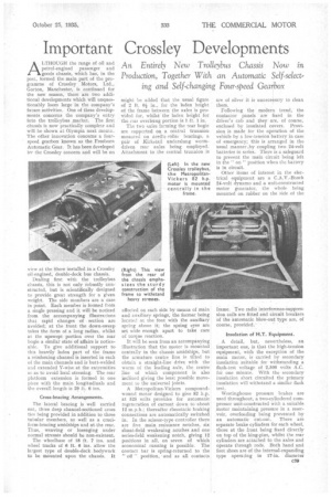
Dealing first with the trolleybus chassis, this is not only robustly con-' structed, but is scientifically designed to provide great strength for a given weight. The side members are a case in point. Each member is formed from a single pressing and it will be noticed from the accompanying illustrations that rapid changes of section are avoided; at the front the down-sweep takes the form of.a long radius, whilst at the upswept portion over the rear bogie a similar state of affairs is noticeable. To give additional support to this heavily laden part of the frame a reinforcing channel is inserted in each of the main channels and is butt-welded and extended Y.-wise at the extremities so as to avoid local stressing. The rear platform extension is formed in one piece with the main longitudinals and the overall length is 29 ft. 6 ins.
Crass-bracing Arrangements.
The lateral bracing is well carried out, three deep channel-sectioned cross ties being provided in addition to three tubular members, as well as a cruciform-bracing amidships and at the rear. Thus, weaving or lozenging under normal stresses should be non-existent.
The wheelbase of 18 ft. 7 ins, and wheel tracks of 6 ft. 6 ins, allow the largest type of double-deck bodywork to be mounted upon the chassis. It might be added that the usual figure of 2 ft. 01 in., for the laden height of the frame between the axles is provided for, whilst' the laden height for the real overhung portion is lit. 1 in.
The two .xles forming the rear bogie are supported on a central trunnion mounted on needie-rollef bearings, a pair of Kirkstail underslung wormdriven rear axles• being employed.Attachment to the central trunnion is
effected on each side by means of main and auxiliary springs; the, former being located at the foot with the auxiliary spring above it; the spring eyes are set wide enough apart to take care of torque reaction.
It will be seen from an accompanying illustration that the motor is mounted centrally in the chassis amidships, but the armature centre line is tilted to obtain a straight-line drive with the worm of the leading axle, the centre line of which component is also inclined giving the least possible movement to the universal joints.
A Metropolitan-Vickers compoundwound motor designed to give 82 h.p. at 525 volts provides for automatic regeneration of current down to about 12 m.p.h.; thereafter rheostatic braking connections are automatically switched in. In the scissor-type controller there are five main resistance notches, six shunt-field weakening notchesi and one series-field weakening notch, giving 12 positions in all, on seven of which economical running is possible. The contact bar is spring-returned to the " off" position, and as all contacts are of silver it is unnecessary to clean them.
Following the modern trend, the contactor panels are fixed in the driver's cab and they are, of course, enclosed by insulated GOVeTS. Provision is made for the operation of the vehicle by a low-tension battery in case of emergency; this is arranged in the usual manner by coupling two 24-volt batteries in series. There is a safeguard to prevent the main circuit being left in the " on " position when the battery is in circuit.
Other items of interest in the electrical equipment are a C.A.V.-Bosch 24-volt dynamo and a unit-constructed motor generator, the whole being mounted on rubber on the side of the frame. Two radio interference-suppression coils are fitted and circuit breakers of the automatic blow-out type are, of course, provided.
Insulation of H.T. Equipment.
A detail, but, nevertheless, an important one, is that the high-tension equipment, with the exception of the main motor, is carried by secondary insulation suitable for. withstanding a flash-test voltage of 2,500 volts A.C. for one minute. With the secondary insulation short circuited the primary insulation will withstand a similar flash test.
Westinghouse pressure brakes are used throughout, a two-cylindered compressor unit-constructed with a suitable motor maintaining pressure in a reservoir, overloading being prevented by an automatic cut-out. There are separate brake cylinders for each wheel, those at the front being fixed directly on top of the king-pins, whilst the rear cylinders are attached to the axles and operate through rods. Both hand and foot shoes are of the internal-expanding type operating in 17-in. diameter drums. The pedal operates brakes on all six wheels, whilst the hand brake operates on the rear wheels alone, applying the same shoes as the foot brake. The rear shoes are 6 ins, wide, those at the front having a width of ins.
The New Automatic Gear.
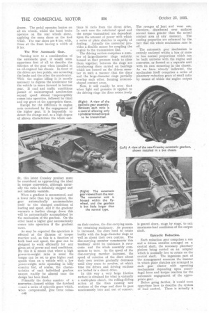
Turning now to a consideration of the automatic 'gear, it would seem opportune first of all to describe the function of the gear when installed in an oil-engined bus chassis. In front of the driver are two pedals, one actuating the brake and the other the accelerator. With the engine idling it is merely necessary to depress the accelerator for the vehicle to move forward in bottom gear. If road and traffic conditions permit of uninterrupted acceleration second speed almost •imperceptibly comes into operation, followed by third and top gears at the appropriate times.
Except for the difference in engine note occasioned by the engagement of the higher gear, it is impossible to detect the change and, as a high degree of silence characterizes the whole out
fit, this latest Crossley product must be considered as approaching the ideal in torque conversion, although naturally the ratio is definitely stepped and not infinitely variable.
When a gradient is encountered, and a lower ratio than top is required, the gear automatically accommodates itself to the changed conditions of loading and speed, and if the gradient warrants a further change down this will be automatically accomplished by the mechanism of the gearbox. On the other hand a higher gear automatically comes into operation if the gradient eases.
As may be expected the operation is effected at the dictates of torque reaction and, as this is a function of both load and speed, the gear can be designed to work efficiently for any given set of power and road conditions. By this it is meant that where a high power-to-weight ratio is usual the torque can be set to give higher road speeds than on a vehicle with a low power-weight ratio operating in hilly country but, of course, the characteristics of each individual gearbox cannot readily be altered once the design has been fixed.
Primarily the device consists of a converter—housed within the flywheel —and a series of epicyclic gears which, when compounded, give three reduc c40 tions in ratio from the direct drive. In each case the rotational speed and the torque transmitted are dependent upon the amount of power with which a series of plate clutches is capable of dealing. Actually the converter provides a flexible means for coupling the engine to the transmission line.
The driving section comprises a number of large-diameter rings suitably housed so that pressure tends to close them together; between the rings are interleaving discs carried on bearings which are housed on the driven member in such a manner that the discs and the large-diameter rings partially overlap each other, forming crescentshaped contact areas.
Now, it will readily be seen that when light end pressure is applied to the driving rings the discs rotate freely on their centres, the disc-carrying member remaining stationary. As pressure is increased, the discs tend to rotate bodily with the large-diameter rings as well as about their own centres. The disc-carrying member counteracts this tendency until its resistance is overcome and the whole assembly commences to turn. As the speed of the disc-carrying member increases, the speed of rotation of the discs about their own centres gradually decreases until they cease to revolve, at which time the driven and driving sections are locked in a direct drive.
In this way a very large friction surface is obtained for what is virtually a multi-plate clutch, the rolling-sliding action of the discs causing new sections of the rings and discs to pass continuously into and out of contact. The ravages of heat and wear are, therefore, distributed over surfaces several times greater than the actual contact area at any moment. The cooling properties are enhanced by the fact that the whole mechanism runs in oil.
The automatic gear mechanism is entirely enclosed within a box of more or less normal proportions which can be built unitwise with the engine and converter, or formed as a separate unit with its own mounting in the chassis. As we have already indicated, the mechanism itself comprises a series of planetary reduction gears of small ratio by means of which the engine output is geared down, stage by stage, to suit maximum-load conditions of the output shaft, Epicyclic Reduction.
Each reduction gear comprises a sun and a driven annulus arranged on a central shaft, the necessary planetary pinions being carried on an adapter which is normally free to rotate on the central shaft. The ingenious part of the arrangement concerns the manner in which plate clutches are arranged in each gear cluster with operating mechanisms depending upon centrifugal force and torque reaction for the automatic engagement of the appropriate gear. Before going further, it would seem opportune here to describe the system of load control. There is actually a centrifugal control to each of the four forward gears, one being housed in the converter, whilst the others are in the gearbox adjacent to the epicyclic reduction stages. Each centrifugal device is quite straightforward, pivoted weights naturally tending to move outwards with increased intensity as rotational speed is increased; from this force, endpressure is applied to the various plate clutches in the mechanism and the plate loading is so arranged that only a prc-determined torque is transmitted.
As was mentioned earlier, the three epicyclic trains are brought into operation successively for third, second and first speeds, thus all three reductions are compounded for bottom gear, one is eliminated for second speed, two are cut out when third gear is engaged,. and a direct drive is, of course; obtained for top.
Finally we come to the effort by which the automatic selection of the appropriate gear is arrived at. It will be understood, of course, that the centrifugal action of the clutch-engaging mechanisms is dependent. upon revolution speed, the size of the weights and
their leverage, or moment, whilst the clutch capacity for transmitting torque further depends upon the leverage of the mechanism connecting the flying weights to the thrust buttons on the end pressure-plate of each clutch.
In order to bring into operation the planetary gearing each carrier-member is adapted to engage the fluid casing through what is virtually a pawl and ratchet arrangement. In the particular application under review three wide fingers (placed close together to prevent he carrier-member increasing speed when it reverses its direction of niction) arenormally held out of engagement h'y oil flung out of the revolving parts. Between each ratio is a load control to govern the locking and releasing of the carrier-member, allowing a predetermined torque only to be transmitted. When any load in excess of this predetermined amount occurs, the carrier-member ceases to rotate and tends to move backwards, engaging a sprag so that the planetary pinions commence to rotate about their own axes, thus introducing a reduction of ratio.
So soon as the load carried by the gearing is small enough to he dealt with by one less ratio the carrier
member Of one set of planetary pinions automatically disengages the 'casing (because the reduction in torque transmitted allows the carrier-member to revolve again) and, by the centrifugal action, of the control presses the driving clutch together and so forms a
solid drive. •