


HINTS ON MAINTENANCE.
Page 28
Page 29
If you've noticed an error in this article please click here to report it so we can fix it.
How to Get the Best Out of a Vehicle, to Secure Reliability and to Avoid Trouble.
CONTRIBUTIONS are invited for this page from fleet managers, drivers, garage foremen and
, mechanics, works staff and draughtsmen, and 'will be paid for on a generous scale. Every system, make, and type of commercial motor vehicle will be dealt with, and the matter should be written with a view to the disclosure of workshop and garage practice in the maintenance of a vehicle—practices which, whilst they may be quite normal, are peculiar to the particular veincle and may not be generally known to those responsible for its running. Expedients and suggestions for overcoming roadside and other troubles are covered in the following page, headed "Roadside and Garage." Communications should be addressed to "The Editor, The Commercial Motor, 7-15, Rosebery Avenee, London, E.G. L"
106.— Testing Magneto Armatures.
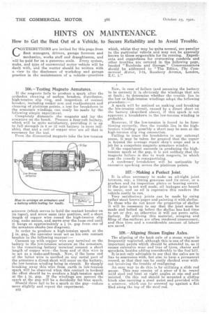
If the magneto fails to produce a spark after the orthodox cleaning of carbon brushes, distributor, high-tension slip ring, and inspection of contact breaker, including rocker arm and readjustment and cleaning of platinum points, a test for breakdown in the armature windinge can easily be made by the following simple experiment. Completely dismantle the magneto and lay the armature on the bench. Procure a four-volt battery, which will be quite satisfactory, providing it is up to full strength (a 6 or 12 volt battery is more reliable), that and a coil of copper wire are all that is necessary for the test.
From the dismantled magneto take the low-tension
setscrew (which serves to hold the contact breaker on its taper), and screw same into position, coil a short length of copper wire, round the high-tension slip ring, make secure, and curve over the.Ioose end until it hangs at approximately a. I in. gap from one of the armature cheeks (see diagram).
In order to produce a high-tension spark at the in. gap, the operator must act as his own contact breaker in the following manner:— Connect up with copper wire any terminal on the battery to the low-tension setscrew on the armature, to the remaining battery terminal connecta short length of copper wire—the loose end of this wire is to act as a make-and-break. Now, if the loose end of the latter wire is earthed on any metal part of the armature a direct short will occur on the battery, the low-tension winding being in circuit. By sharply breaking away this wire from earth (a low-tension spark will be observed when this contact is broken) the effect should he to produce a high-tension spark at the in. gap. If the windings are correct the spark at the gap will be a decidedly fat blue spark. Should there fail to be a spark at'the gap—reduce same slightly and repeat the experiment. Now, in case of failure (and assuming the battery to be correct) it is obviously the windings that are at fault ; to determine whether the trouble lies in the low or high-tension windings adopt the following procedure:—
A spark will be noticed on making and breaking the low-tension circuit, caused by a direct short on the battery (described above)' if this spark is not apparent a breakdown in the low-tension winding is probable.
However, if the low-tension is found to be functioning correctly, then the trouble lies in the hightension winding—possibly a short may be seen at the high-tension slip ring connection.
Failing to trace the breakdown to any external cause, it may be taken for granted that the repair is beyond the average repair shop's scope and is a job for a competent magneto armature winder.
If the experiment succeeds in producing the hightension spark at the gap, it is not unlikely that the magneto failure is due to weak magnets, in which case the remedy is remagnetizing.
A condenser breakdown will be noticeable by excessive sparking across the platinum points.
107.—Making a Perfect Joint,
It is often necessary to make an oil-tight joint hetwecn, say, a timing geare,ase and its cover, or a gearbox and its inspection plates or bearing covers. If the joint is not well made, oil leakages are bound to occur, and as oil is expensive this renders the vehicle costly to run.
Very satisfactory joints can be made by using rather stout brown paper and painting it with shellac. To those who do not know the properties of shellac it will be necessary to say that the joint must be made and bolted up before the shellac has had time to set or dry. as otherwise it will not prove sat isfactory. By utilizing this material, scraping and filing of thee.aurfaces are often rendered unnecessary, and thus time and a considerable amount of labour are saved.
108.—Aligning Stearn Engine Axles.
The aligning of the back axle of a steam wagon is frequently neglected, although this is one of the most important points which should be attended to, as it causes extensive wear and tear of tyres, chains and sprockets, besides adding considerably to the fuel bill. It is not only advisable to see that the axles are in line to commence with, but also to keep a permanent record, so that they can be easily checked over without involving the trouble of realigning.
An easy way to do this is by utilizing a slide rod gauge. This may consist of a piece of in. round mild steel rod bent at right angles at one end and pointed. ' On this rod should be mounted a sliding block also carrying a steel point and provided with setscrew, which can be screwed up against a flat filed along the top of the steel rod. Having made sure that the axles are in line, a deep centre punch mark should be made on the bracket of the radius rod. he fixed end of the gauge should be pressed into, this mark, another mark scribed on the radius rod and a similar punch mark made at this point. The radius rod and bracket on the off side should be marked in a similar manner. At any future time when it becomes necessary to take up the slackness of the chain, by keeping the centre punch marks equidistant at each side of the vehicle, the axle can always be maintained parallel to its former position.
109.—Testing Slide Valves on Yorkshire Wagon.
The L.P. and HA). slide valves on -the Yorkshire steam wagon should be tested periodically. To deal with the former, place the reversing lever in " mid " position, and the L.P. crank at threequarters stroke, open the regulator slightly, throw open one of the smokebox doors and press down the by-pass valve. If steam is thin emitted through the nozzles the slide valve is leaking. To test the H.P. valve, place the reversing lever in " mid " position as betore, but this time the H.P. crank must be placed at three-quarters stroke; open the regulator a little and then the drain cock on the L.P. cylinder steam chest, and if steam comes out the slide, valve is leaking. The remedy in either case is to reface and scrape the valves and their -faces.
110.---A Cause of Seizing Up.
It may not have occurred to many users of commercial motor vehicles that an engine may quite possibly seize up whilst just ticking over and with the vehicle at al Standstill. This usually happens only with engines in which splash lubrication is employed. In a recent instance a practically new lorry was left standing on a steep hill for a short time. The engine was running very slowly. Within a short time the piston of the rear cylinder seized and it was found that this was due to the fact that, whilst standing on a hill, the rear cylinders were being starved of oil, although the front cylinder was receiving rather more than its share.