


Patents Completed.
Page 24
If you've noticed an error in this article please click here to report it so we can fix it.
Abridgments of Interesting Specifications.
SPEED GEAR.-Kirku p.—N . 206, dated January 3rd, 1906.—This gear provides three speeds and a reverse. The driving shaft (13) has a sliding extension /131). Free on this extension three bevel pinions (Di) and (Di) are mounted, and these mesh with three bevel wheels (Al) (Al) and (A3), carried by the clifferen • tial gear. The shaft has on it elaivs (51), which engage with corresponding recesses in the pinions (Di) (Di), and thus, driving is effected through one or other of these pinions for the first and second speeds.
Sliding on the extension (Bxj is a sleeve (E), having jaws adapted to engage the pinion (Di), whereby the third speed is obtained. On the sleeve is a wheel (K) adapted to be brought into mesh with a wheel (f) gearing with another wheel (II) on a counter-shaft (0). At the other end of the counter-shaft a bevel pinion (B4) is mounted, and engages a wheel (A4) on the differential gear. When the sleeve (El is moved to bring the wheel (IC) into mesh with the wheel (J) a reverse drive is obtained.
VALVE GRINDING MACHINE. — Ridley.—No. 275, dated January 4th, 1906. —The machine is provided with a standard (A), upon which a sliding table iP) is mounted. Carried by the standard is a telescopic rotatable shaft (C) having a flexible portion (Cl). The engine, of which the valves are to be ground, is mounted on the table (P), and one of the valves indicated at (N) is brought beneath a tool (D). The tool is chisol-ed4ed to engage the, notch in the top of the valve, and as the shaft (C) rotates, the valve is courespondingly rotated. An adjustable member (M) is carried in the table (P), and is free to slide in a socket (L). A tappet (0), oscillated by a rod (H), lifts the member (M) at each rotation of the driving shaft (02) of the machine, and thus the valve (N) is constantly lifted and rotated during grinding.
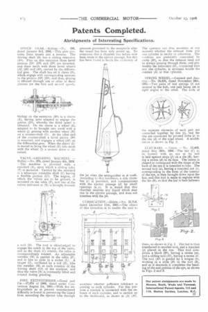
FIRE EXTINGUISIIER.—Graaf and Cie.-17,074 of 1906, dated under Con. tention August 1st, 1903.—With fire extinguishers as at present manufactured difficulty is found in preventing the liquid from ascending the ejector tube through
pressure generated in the receptacle after the vessel has been duly sealed up. To overcome this a chamber has before now been made in the ejector passage, but this has been found to break the contineity of the jet when the extinguisher is at work. According to this invention, a side chamber (e) is provided, and communicates with the ejector passage (d) by small openings (u, v). It is stated that this chamber receives any liquid which may rise in the ejector passage, and does not interfere with the jet.
LUBRICATION.—Shiels.—No. 25,758, dated December 11th, 1905.—The object of this invention is to enable the user to
ascertain whether sufficient lubricant is passing to each cylinder. For this purpose a conduit is connected with the exhaust of each cylinder, and is carried up to the dashboard, as shown at (A) (Al).
The operator can thus ascertain at any moment whether the exhaust from any one cylinder is smoky or otherwise. The conduits are preferably controlled by cocks (131), so that the exhaust need not be always passing through them, and preferably the lubricator (H), connected, with any one Cylinder, is arranged beside the conduit (A) of that cylinder.
SPRING WHEEL.—Garrard and Another.—NO. 24,050, dated November 28th, 1905.—Two pairs of 'leaf springs (5) are secured to the hub, one pair being set at right angles to the other. The ends of the separate elements of each pair are connected together by ties (e), and the ties are connected by pivoted links (e) to the rim (d) of the road wheelA modificatien is shown in Fig. 2.
STAY-BARS. — Green. — Nu. 12,459, dated May 29th, 1906.—The bar (C) to be formed with an eye at its end is laid against stops (f) on a die (B), having a recess (d) in its face. The recess is shaped to correspond with the shape of the back of the eye it is intended to take. The second tool (a), baying a rounded nut (e), corresponding to the form of the interior of the eye, is then brought down upon the bar, and this tool is made to register with the die (B), so that the bar is bent between them, as shown in Fig. 1. The bar is then transferred to another tool, and a mandrel (p) placed in the eye. This tool comprises a block (Eli, having a recess (m), and a sliding tool (Al), having a recess RI. The tool (Al) is guided by a tongue (h), working in a slide (hi) in the tool (B), and as it descends it completes the bending of the end portion of the eye, as shown in Figs. 2 and 3.