


Compact Disc Brakes
Page 78
If you've noticed an error in this article please click here to report it so we can fix it.
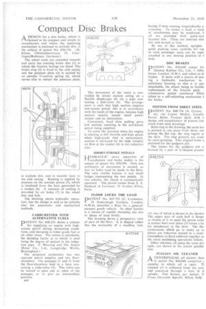
A DESIGN for a disc brake, which is PA claimed to be compact and simple to manufacture and where the operating mechanism is enclosed to exclude dirt, is the subject of patent No. 850,770. (H. Klaue, Christopherstrasse 19, Uberlingen/Bodensee, Germany.)
The, wheel studs are extended inwards and carry the rotating brake disc (1) to which the friction facings are fitted. The brake ring (2) is fixed to the axle casing and the pressure plate (3) is carried by an annular U-section spring (4), which serves also to retract the pressure plate, to .exclude dirt, and to transfer heat to the axle casing. Braking is applied by pressure on the annular piston (5), which is insulated from the heat generated by a washer (6). A measure of cooling is provided by air holes (7) in the wheel disc and hub.
The drawing shows hydraulic operation, but the design is said to be suitable also for pneumatic and mechanical methods.
CARBURETTER WITH ALTERNATIVE FUELS
PATENT No. 848,353 shows a scheme for supplying an engine with high. octane petrol during detonating conditions, and changing to lower grade fuel at all other times. The action is automatic. the deciding factor as to which is used being the degree of suction in the induction pipe. (I. Weaving and The Austin Motor Co„ Ltd., Longbridge Works, Birmingham.) The proposed carburetter has two separate petrol supplies and two floatchambers. The passages (1 and 2) from the float-chambers lead to a bore containing a slide-valve (3). The valve can be moved to open one or other of the passages, or to give an intermediate position.
B 44
The movement of the valve is controlled by intake suction acting on a flexible diaphragm (4) via a pipe containing a ball-valve (5). The arrangement is such that high suction supplies low-octane petrol; this is in accordance with the needs of the engine, because high suction usually means small power output and no detonation.
Conversely, hard slow pulling gives low suction, resulting in the anti-knock petrol being supplied.
To cover the occasion when the engine is running at full throttle and high speed, when high-grade fuel is unnecessary, suction is increased by the high velocity air flow at the venturi (6) in the induction pipe.
SHORT-STROKEPEDALS LIYDRAULIC servo operation of accelerator and brake pedals is the subject of patent No. 850,996. Only one millimetre of movement is needed, so that no holes need be made in the floor. The only visible feature is two small bulges representing the two pedals. In this scheme, the clutch is automatically operated. The patent comes from S. A. Panhard et Levassor, 19 Avenue d'Ivry, Paris.
FLOOR LOCKS THE LOAD
PATENT No. 847,792 .(C. Landsman, 29 Endersleigh Gardens, London, N.W.4), describes a floor for a generalpurpose goods vehicle. Its chief feature is a means of rapidly clamping any size or shape of load firmly.
The drawing shows a perspective view of part of the floor. It is shaped rather like the worktable of a machine tool,
having T-slots running longitudinally a. crosswise. To secure a load, a varic of attachments may be employed, b all are provided with quick-acti bayonet feet. These are inserted into slot and turned to lock.
By use of this method, uprights guide packing cases, eyebolts for ror or even passenger seats can be rapiC attached at any desired position in t slots.
DISC BRAKES
PATENT No. 850,648 comes frc Dunlop Rubber Co., Ltd., 1 Alba Street, London, N.W.1, and refers to di brakes. It deals with a means of sect ing a hydraulic mechanism to stationary housing so that it is easi detachable, the object being to facilitz replacement of the friction pads. consecutive patent numbered 850,6 refers to a self-adjusting mechanism f the brake.
PISTONS FROM SHEET STEEL
PATENT No. 848,734 (A. Cornet, ter, rue Louise Michel, Levallo Perret, Seine, France) deals with t design and manufacture of pistons tab cated from steel pressings.
Referring to the drawing, the main bos is pressed in one piece from sheet, cor prising the flat top, the ring region at the skirt. The ring grooves are creat by axial pressing. Two aligned holes a punched for the gudgeon pin.
The bosses for the gudgeon pin a formed by a pair of U-shaped pressin:
(I), one of which is shown in the drawin The upper part of each half is flange as shown at 2, to meet the piston crow A similar bent-over piece (3) forms a fa4 for attachment to the skirt. The thr4 components which go to make up oi piston are induction brazed in a neutr atmosphere or hard soldered together at: the usual machining operations follow.
Other schemes, all using the same prii ciple, are shown in the patent specific, tion.
ITALIAN OIL CLEANER
riA CENTRIFUGAL oil cleaner shoe • in patent No. 844,046 comprises annulus in which oil is spun. Ti cleaned oil is collected from the cent and conveyed through a bore ill tl spindle. Fiat Societa per Azioni, 21 Corso Giovanni Agnelli, Milan, Italy.