


Steering Track-laying Tractors
Page 68
If you've noticed an error in this article please click here to report it so we can fix it.
A Résumé of Recently Published Patent Spe cifications
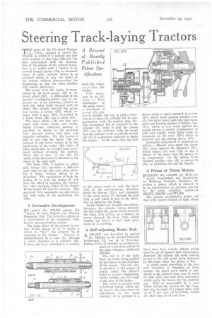
MHE name of the Cleveland Tractor Co., U.S.A., appears in patent No. 381,974, in which it is pointed out that with traettrs of this type difficulty has been experienced with the steering. One of the objects of the present invention is to "enable such a tractor to be steered around curves with an extensive range of radii; another object is to transmit power to only one wheel of the tractor without disconnecting the mechanism, so that the other member will remain stationary.
The power from the engine is transmitted by the bevel pinion (13) to the crown wheel (23). A differential of the parallel overlapping-pinion type is employed, one of the planetary pinions on each side being made integral with its shaft ; this extends through the casing and carries a pinion (24), which engages with a gear (25), Controlled by a brake drum (26) and a band (27).
The inner shafts (14) are also provided with brake drums and bands, whilst further reduction gearing is provided, as shown in the sectional view through pinion and gear and epicyclic reduction. By this means it will be seen that the shafts (14) are relieved of any heavy torque, so by the apPlioation of the brake (40) either of these shafts may be arrested from movement without stressing the gearing. When this is done on one side the whole of the movement is diverted to the wheel at the other side.
The brake (27), if applied on either side, brings into operation a different gear ratio on one side only, thus allowing a larger turning radius to be described. The application of both the brakes 40 or both the brakes 27 will have the effect of stopping the tractor, but when applying either of the brakes 40 the brakes 27 must be released. The sectional view represents one side alone, but both sides of the mechanism are alike.
A Dewandre Development.
IN patent No. 382,023 appear the names of Jules Pagard and Clayton Dewandre, Ltd. The invention relates to a development of the company's wellknown. vacuum-braking, system.
The main object of the present invention would appear to be to enable a driver to "feel" the pressure he. is
applying to his brakes. Vacuum is communicated by a pipe (8), through a valve Chamber to a cylinder (9), 5 being the lever attached to a rocking shaft (6), which applies the brakes.
T h e operation is as follows: — The depression of the pedal causes a movement of a rod (3) relative to another rod (4), in such a direction as to place the cylinder (9) in communication with the suction pipe (8). The consequent fall of pressure in the cylinder (9) tends to pull the piston (13) into the cylinder, with the result that the cylinder tends to pull the second rod (4) in a direction required to apply the brakes. At the same time, the pull of the piston tends to rock the lever (10) in the anti-clockwise direction about its fulcrum (11a), and transmits to the valve easing (7) through the link (14), a pull which is also in the direction of applying the brake.'
As the brakes are brought into action, 'therefore, the cylinder moves towards the left whilst the piston moves towards the right, thus setting up a balance of power through the fever (10), which enables the driver to feel what pressures he is exerting.
A Self-adjusting Brake Rod. A BRAKE rod described in patent'
No. 382,118, by the Societe Generale Is.othermos, 12, rue de la Tour-desDames, Paris, is intended as an improvement on a previous patent of the same company, numbered 365,885.
The rod is of the push kind, the brake being applied by movement in the direction of the arrow. The rod (4a) is attached to the source of power, either the driver's pedal or a servo mechanism, whilst another rod (la) leads to the shoe of the brake.
The rod 1a is screwed with a buttress thread, which can be used in the first place for adjustment in the usual manner ; 4" is screwed to a
sleeve which is again screwed to a cone (7a), which bears against another cone (5), the latter being split into four equal parts and bearing against a further cone (8a), which in turn bears against the .spring shown, a similar arrangement of split and unsplit cones being made to terminate on the cone (15a) which is screwed into the sliding sleeve (17).
Automatic adjustment is produced as follows :—Should wear occur the sleeve (17) bears against the abutment (21), which causes one cone (12) to slip a thread of the screw and the „spring to be compressed. On the spring, being released another cone (5) is caused to slip, so adjusting the rod for length.
A Piston of Three Metals.
PATENT No. 382,066, by Elektron metall Gesellschaft mit Deschrankter Haftung, Canstatt, Germany, describes a piston which is claimed to be an improvement on previous patents by the same company, numbered 295,971, 288,543 and 271,454 .
The present specification points out that with pistons formed of light alloys there have been certain defects which must be set off against their advantages. Amongst the defects the most serious is due to the soft metal being daamged by the rings when the piston is hot.
A piston made according to the present invention is composed of three metals: the upper part, which is subjected to the greatest heat, may be made of light alloy and may have extensions which carry the bosses for the gudgeon pin. This is surrounded by a part which carries the grooves for the rings, and may be made of a copper alloy with up to 5 per cent. of beryllium, whilst the skirt may be of cast iron.