


CATERPILLAR CONVERSION ,UNITS
Page 40
If you've noticed an error in this article please click here to report it so we can fix it.
A Résumé of Recently Published Patents.
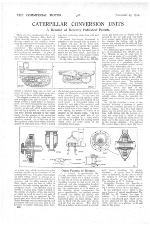
There are two specifications this week by Caterpillar Tractors, ltd., both of which describe means for replacing the driving wheels of the ordinary motor lorry by self-contained caterpillar tracks.
In No. 133,469 a live axle chassis is considered. The existing road wheels, complete with their hubs, huh-caps, and driving dogs, are removed. In place of each wheel is fitted a sleeve or false hub, and on each of these slips the caterpillar track mechanism, the fastening being merely a bayonet type one, so that, on paper at least, it would seem to he easy to fit one of these caterpillar adapters. The adapter consists of a doubly flanged and strongly-made hub or sleeve. ;One flange carries a light frame or distance pieee, the other supports the gear casing.: The _casing and the frame are coupled together at the end, which is remote from the hub by a spindle on which revolves the main driving sprocket of the chain track. In this manner is the permanent .parallelism of the driving gear and the sprocket assured. On to the end of the driving shaft of the lorry slides a suitably splined or keywayed bass, which is bolted to a gear ring which revolves on roller bearings carried by an extension of the existing axle case. The gear ring engages an idler wheel; which is carried on a spindle supported by the two walls of the gearcase, and the idler meshes with a third wheel, upon the boss of which is secured the main driving sprocket of the caterpillar track. The sprocket itself is merely a toothed ring which is bolted to the outside of a hollow drum, the interior of which is bored to receive two sets of brakes which may be operated by the. brake gear with which the lorry is fitted. Roller bearings are fitted throughout, and particular attention-has been paid to the problem of totally enclosing these bear B38 ing• and protecting them from grit and moisture.
A second fork-shaped framework is attached to the flanged hub by means of a radius rod pin. At its front end, between the fork, it carries the leading wheel for the chain of the track. Below, it efts an a support for the usual type of rollers for the chain track. Prevision is also made for similar but smaller rollers to support the upper run of the chain.
In the other specification, No. 133,382, •
the driving gear is more suitable for application tO-a, chassis in which the final drive is by internal gears. In this 'case the main chain-track driving sprocket -slides on to the axle of the lorry instead of the road wheel. A fork-ended radius rod passes by each side of the sprocket, and is„ also supported by the axle. Its front end is fitted with a short length of laminated spring, by means of which it is secured to the chassis frame. The two radius rods, one on each side of the vehicle, are coupled by a shaft which also serves as a pivot for rocking levers whi.ch carry the roller frame of the caterpillar track gear.-
Other Patents of Interest.
=J. Linzell, in specification No.
133,396, describes what he refers to as compound wheel for a motor vehicle,
• by the use of which he anticipates that smoother Tanning on bad roads will be achieved, and -also comparative freedom from vibration and skidding. Considering the construction as it is shown on the drawing which accompanies the, patent specification, the patentee mounts a second axle behind the driving axle proper, as close to it as possible, and supported upon the same spring. Each axle is fitted with the same size wheels, and all four are driven. The idea is that as a hollow in the ground is encoun tered, the front pair of wheels will be carried to the far side and will reach level ground again before the rear pair has reached the hollow' afid in that manner the vehicle will be relieved from the necessity to follow the contour of the road surface.
The differential gear which is the subject of specification No. 133,397, by F. Von Elbertz, is one of that type in which use is. made of eccentrically disposed gears. One differential shaft carries a pinion which meshes with the internal teeth of a gearwheel Which is supported in an eccentrie spider carried by the other differential shaft.
The internal gear has also teeth on its exterior surface, and they goat with another gear which is bolted to the interior of the differential case. The la.stnamed gear is concentric to the differential `shafts,' and therefore 'eccentric to the -other internal gear. For ordinary straightforward running the internal gear, which is bolted to the differential' gearcase, drives the rest of the mechanisrn round solid, . When rounding a corner the differential shaft, which is Coupled to the outer wheel. of the vehicle, either allows the .eccentric internal, gear to overrun the pinion, or vice versa.
_No, 13,3,582 describes a form of carburetter whereby a mixture of petrel vapour and acetylene gas mav be drawn into the engine. The two fuel supply pipes, one for petrol and one for acetylene, both 'deliver into the bottom of a case, the lower half of which is fitted with wicks, up .which the fuels travel on their way to the upper half which serves as the muting chamber. For starting the engine draws direct from the lower
half, short ciriniting the mixing chamber, A special form of throttle valve is indicated, by the use of which the suction is diverted either to the mixing chamber or the fuel chamber. The patentee is M. T, Graham.
Caterpillar Tractors, Ltd., describe in No. 133,402, a. method of totally enclosing a friction clutch of the disc type.
In the induction valve, which is the main feature of 'patent specification No. 133,335, by M. Sizaire, the stem is tubular. It is screwed externally to receive a cup-shaped part which serves as one abutment for the spring of the valve, and also as al plunger to fit and slide in the guide.