


Patents Completed.
Page 20
If you've noticed an error in this article please click here to report it so we can fix it.
Sheppee Non-skid for Twin Tires, Improved Albion Lighting Switch.
fvIerryweather Connecting Rods. Adjustable I/dive lappets.
Copies of complete spectfications of the patents published on this page can be obtained from the Sales Branch, Patent Office, Holborn, W.C., at the cost of sixpence for each specification.
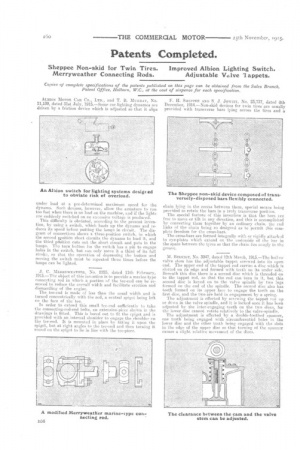
ALBION MOTOR CAR Co., LTD., and T. B. MURRAY, No. 11,139, dated 31st July, 1915.—Some car-lighting dynamos are driven by a friction device which is adjusted so that it slips
under load at a pre-determined maximum speed for the dynamo. Such devices, however, allow the armature to run too fast when there is no load on the machine, and if the lights are suddenly switched on an excessive voltage is produced. This difficulty is obviated, according to the present invention, by using a switch, which loads up the dynamo and reduces its speed before putting the lamps in circuit. The diagram of connections shows a three-position switch, in which the second npsition short circuits the dynamo to load it, and the third position cuts out the short circuit and puts in the lamps. The turn button for the switch has a pin to engage holes in the switch, but can only move it a third of its full stroke, so that the operation of depressing the button and moving the switch must be repeated three times before the lamps can be lighted.
J. C. MEnnywEATirgn, No. 2225, dated 11th February, 1915.—The object of this invention is to provide a marine type connecting rod in which a portion of the tee-end can be removed to reduce the overall width and facilitate erection and dismantling of the engine. The tee-end is made of less than the usual width and is turned concentrically with the rod, a central spigot being left on the face of the tee.
In order to extend this small tee-end sufficiently to take the conneeting-red-end bolts, an extension-piece shown in the drawings is fitted. This is bored out to fit the spigot and is provided with an internal shoulder to engage the shoulder on the tee-end, It is mounted in place by fitting it upon the spigot., bet at right angles to the tee-end and then turning it round en the spigot to lie in line with the tee-piece. F. H. SHEPPEY'. AND S. J. Jowirr, No. 23,737, dated 8th December, 1914.—Non-skid devices for twin tires are usually provided with transverse bars lying across the tires and a
chain lying in. the reeoss between them, special means being provided to retain the bars in a truly transverse position.
The special feature of this invention is that the bars ere free to move or tilt in any direction, and this is accomplished by connecting them together by an ordinary chain, the end links Of the chain being SO designed as to permit this complete freedom for the cross-bars.
The cross-bars are formed integrally with or rigidly attached to eye-plates which extend en the underside of the bar in the space between the tyres so that the chain lies snugly in the groove.
M, BIRKIGT, No. 3947, dated 12th March, 1915.—The hollow valve stem has the adjustable tappet screwed into its open end. The upper end of the tappet rod carries a. (bee which is slotted on its edge and formed with teeth On its under side, Beneath this disc there is a second disc which is threaded on to the tappet rod, so that the rod can turn in it, but this second disc is keyed on to the valve spindle by two lugs formed on the end of the spindle. The second disc also has teeth formed on its upper face to engage the teeth on the first disc, and the two are held in engagement by a spring.
The adjustment is effected by screwing the tappet rod up or down in the valve spindle, and it is locked once it has been adjusted by the inter-engaging •teeth on the two discs, for the lower disc cannot rotate relatively to the valve-spindle.
The adjustment is effected by a double-toothed spanner, one tooth being engaged with circumferential holes in the lower disc and the other tooth being engaged with the slots in the edge af the upper disc so that turning of the spanner causes a slight relative movement of the discs.