


The compression ignition engine, 11
Page 70
If you've noticed an error in this article please click here to report it so we can fix it.
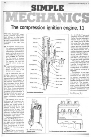
THE FUEL INJECTION system on the Cummins engine is entirely different to those already discussed in this series. Known as the PT (pressure-time) system it consists of two main cornponents: (a) an injector which creates the pressure required for the injection of the fuel which is mechanically operated by a push rod and rocker arm actuated by the engine camshaft. (Figure 1). The cam for the injector is situated between the cams needed for opening the inlet and exhaust valves on the engine.
(b) a combined low pressure pump and governor unit which delivers fuel at low pressure to the injector.
Fuel is drawn from the fuel tank by a gear-type lift pump and then pressure-regulated by a governor and throttle control. It then travels at low pressure to the injectors, where the pressure is increased. At the appropriate moment the fuel is fed into the cylinder in an atomised form. When the plunger injector is in certain positions, the fuel circulates through passages in the injector body and returns to the tank, purging air from the system and keeping the injector cool.
The metering of the fuel depends upon (a) the pressure developed in the pump, which is variable, and a fixed orifice in the injector and (b) the time interval during which the metering orifice is open. This depends on engine speed. Quite obviously, the faster the engine is running, the shorter will be she time the orifice is open.
The Detroit Diesel engine fitted to the TM Bedford uses an other type of fuel injection sys tem, again with a mechanically operated injector, actuated. as in the Cummins type, by a cam integral with the main engine camshaft.
Figure 2 gives a schematic diagram of this system as fitted to a six-cylinder V-type engii Following the course taken the fuel from the fuel tank tot injectors, it will be seen that fuel travels through a strain fuel pump, filter, fuel pipes a fuel manifolds, the latter bei integral with the cylinder he Surplus fuel passes through t fuel return manifold and cc necting pipes back to the tank restricted fitting installed in t return manifold assists maintaining a pressure in tf part of the fuel system betwe the inlet and outlet manifolds.
The injector itself is a col bined pump and injector unit. is similar in construction toll element of an in-line pump, c scribed earlier in this series, E cept the pump is inverted (s Figure 3).
The quantity of fuel injecti is regulated by two helic, machined in the lower part the plunger, the rotation of tl plunger varying the relationsh between the helices and the fu inlet ports. The plunger rotated by a quadrant ge. which meshes with the contr rack. The control rack from eac injector is connected to a cor mon control tube by levers.
by Preceptor