


A FRENCH VAN CHASSIS FOR 7-CWT. LOADS.
Page 53
Page 54
If you've noticed an error in this article please click here to report it so we can fix it.
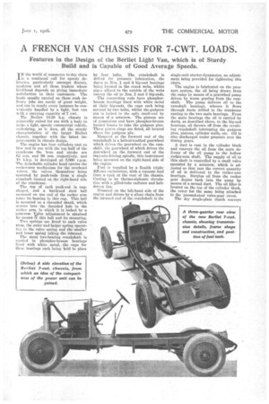
Features in the Design of the Berliet Light Van, which is of Sturdy Build and is Capable of Good Average Speeds.
IN the world of commerce to-day there is a continual call for speedy deliveries, particularly amongst florists, modistes and all those traders whose livelihood depends on giving immediate satisfaction to their customers. The loads usually carried on these rush delivery jobs are rarely of great weight, and can in nearly every instance be conveniently handled by a light, fast van with a carrying capacity of 7 cwt.
The Bernet 10-20 h.p. chassis is admirably suited for use with a body to make a 'light, speedy commercial vehicle, embodying, as it does, all the sturdy characteristics of the larger Berliet chassis, together with the latest improvements in chassis design.
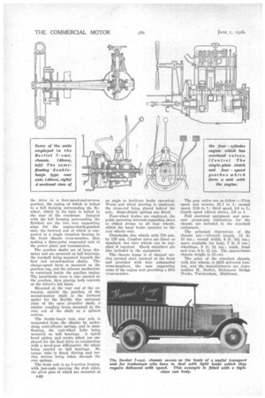
The engine has four cylindera east en bloc and in one with the top half of the crankcase the bore and stroke are 62 mm. and 96 mm. respectively, and iS b.h.p. is developed at 3,000 r.p.m. The detachable cylinder head carries the rocker-arm mechanism for the overhead valves, the valves themselves being 'operated by push-rods from a single camshaft located on the right-hand side of the crankcase.
The top of each push-rod is cupshaped,. and a hardened steel ball mounted on one end of the rocker arm takes its bearing in this cup. This ball is mounted on a threaded shank, which screws into the threaded hole in the rocker arm, in which it is locked by a Setscrew. Valve adjustment is obtained by means i% this ball and its mounting.
Two springs are fitted to each Valve Stem, the outer and larger spring operating' as the valve spring and the Smaller and inner spring taking the rebound.
The stout two-bearing crankshaft is carried in Phosphor-bronze bearings lined with white metal, the caps for these bearings each being held in place by four bolts. The crankshaft is drilled for pressure lubrication, the duets to Nos. 1 and 4 big-end bearings being located in the crank webs, whilst pipes affixed to the outside of the webs convey the oil to Nos. 2 and 3 big-ends.
• The connecting rods have phosphorbronze bearings lined with white metal at their big-ends, the caps each being secured by two bolts, whilst the gudgeon -pin is locked in the split small-end by means of a setscrew. The pistons are of aluminium and have phosphor-bronze bushed bosses to take the gudgeon pins. Three piston rings are fitted, all located above the gudgeon pin. Mounted' at the forward end of the crankshaft is a helical-toothed gearwheel which drives the gearwheel on the camshift, the gearwheel of which drives the gearwheel on the forward end of the magneto-driving spindle, this instrument being mounted on the right-hand side of the engine.
Fuel is supplied by a Zenith triplediffuser carburetter, with a vacuum feed from a tank at the rear of the chassis. Cooling is by thermo-siphonic circulation with a gilled-tube radiator and beltdriven fan.
Mounted on the left-hand side of the engine and driven by a silent chain from the forward end of the crankshaft is the single-unit starter-dynamotor, an adjustment being provided for tightening this chain.
The engine is lubricated on the pressure system, the oil being drawn from the sump by means of a gearwheel pump driven by worm gearing from the camshaft. The pump delivers oil to the camshaft bearings, whence it flows through ducts drilled in the crankcase casting to the two main bearings. From the main bearings the oil is carried by ducts, as described above, to the big-end bearings, oil thrown off from the revolving crankshaft lubricating the gudgeon pins, pistons, cylinder walls, etc. Oil is also discharged under pressure over the timing gears.
A duet is cast in the cylinder block and conveys the oil from the main delivery of the oil pump to the hollow rocker-arm shaft. The supply of oil to this shaft is controlled by a small valve operated by a setscrew, which is adjusted so that just the correct quantity of oil is delivered to the rocker-arm bearings. Surplus oil from the rocker gear drains back into the sump by means of a second duct. The oil filler is located on the top of the cylinder block, the cover for the same being attached to the pressed-steel valve-gear _cover.
The dry single-plate clutch conveys
the drive to a four-speed-and-reverse gearbox, the casing of which is bolted to a bell housing surrounding the flywheel, which in its turn is bolted to the rear of the crankcase. Integral with the bell housing surrounding the flywheel are the two rear supporting arms for the engine-clutch-gearboit unit, the forward end of which is supported in a single trunnion bearing in the front chassis cross-member, thus making a three-point suspended unit of the power plant and transmission.
The gearbox shafts are of large diameter and are mounted on ball bearings, the layshaft being mounted beneath the first and second-motion shafts. The change-speed lever is mounted on the gearbox top, and the selector mechanism is contained inside the gearbox casing. The hand-brake lever is also carried on the gearbox, thus placing both controls at the driver's left hand.
Mounted at the rear end of the extension, outside the gearbox, of the second-motion shaft is the forward spider for the flexible disc universal joint of the open propeller shaft, a similar coupling being mounted at the rear end of the shaft on a plined section.
The double-banjo type rear axle is suspended from the chassis by underslung semi-elliptic springs, and is semifloating, the rear-wheel hubs being mounted on ball bearings. A spiral bevel pinion and crown wheel are employed for the final drive in conjunction with a bevel-gear differential, the whole being carried on ball bearings. No torque tube is fitted, driving and torsion strains being taken through the rear springs.
The front axle is an 1-section forging, with jaw-ends carrying the stub axles, the pivot pins of which are mounted at an angle to facilitate brake operation. Worm and wheel steering is employed, the cross-rod being placed behind the axle. Semi-elliptic springs are fitted.
Four-wheel brakes are employed, the pedal operating internal-expanding shoes in ribbed drums on all four wheels, whilst the hand brake operates on the rear wheels only.
Detachable disc wheels with 730 mm. by 130 mm. Comfort tyres are fitted as standard, but -wire wheels can be supplied if required. Shock absorbers are also included in the equipment.
The chassis frame is of channel section pressed steel, inswept at the front and provided with four substantial cross-members, the rear supporting arms of the engine unit providing a fifth cross-member.
The gear ratios are as follow :—First speed and reverse, 21.1 to 1; second speed, 13.9 to 1; third speed, 8.9 to 1; fourth speed (direct drive), 5.9 to 1.
Full electrical equipment and pressure grease-gun lubrication for the chassis are included in the standard equipment.
The principal dimensions of the chassis are :—Overall length, 12 ft. 10 ins. ; overall width, 4 ft. 101 ins.; space available for body, 7 ft. 5 ins.; wheelbase, 9 ft. 21 ins.; track, front and rear, 4 ft. 31 ins. The approximate chassis weight is 12 cwt.
The price of the standard chassis, with disc wheels, is 215 delivered London, and the manufacturers are Auto
mobiles Berliet, Richmond Bridge Works, Twickenham, Middlesex,