


The Arrangement of the Seating, Staircase, Windows and Ventilation of Double-deck. Buses and the Details of Top Deck Covers.
Page 23
Page 24
Page 25
Page 26
If you've noticed an error in this article please click here to report it so we can fix it.
BUS BODY DESIGN AND CONSTRUCTION.
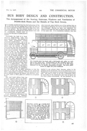
IT is usually considered that the chief advantage of the chassis with the low loading line is that the floor of the bus is reached by fewer and easier steps than with the older pattern. But the modern chassis is also far more suitable for mounting the double-decked body and its introduction should tend to popularize this type of public-service vehicle.
Essentially the body is a back entrance single-decker, with root seats and staircase. The addition of these items necessitates certain structural modifications. As a top load is carried, the framework of the Q) lower saloon is stronger. The side pillars are not always of larger cross-section, but they-are increased in number and the use of windows of large urea is avoided. The ventilat ing rail—that is, the longitudinal member of the side framework immediately below the cantrail at the roof line—is seldom omitted. The. corner pillars, at the ends of the frout and hind bulkheads respectively, are an inch larger each way. The standing pillars on each side of the doorway are half an inch wider than in a single-decker. The presence of a fair number of side pillars gives the opportunity for framing a corresponding number of hoopsticks into the cantrail at the pillar positions, so that the junction of side and roof framing can be reinforced with a steel gusset or bracket. Further hoopsticks are placed midway between the pillars, and alternate ones, at least, have a flitch plate or carline to strengthen them.
The roof itself differs from the ordinary pattern, since it is doubleboarded. This is done for three reasons. The extra substance gives the strength required, and, by using two relatively thin boards instead of one thick plank, a layer of roofing Material can be inserted to make it waterproof where it does not come in contact with the passengers' feet. Two thin boards are more easily manipulated than one more rigid.
If any additional stiffening of the general framework be required, apart from its reinforcement by suit
•
able ironwork, some builders are of the opinion that an advantage is gained by the way in which the side pillars are arranged. Having an open rear platform, the whole of the body side may be spaced out with windows of the same size. It is considered, however, that this method is not always ideal, because, owing to the presence of the wheel-arch, one or two pillars have to be framed into it and cannot be carried down to the bottom side. One way is, first, to set out a full-length pillar on each side of the wheel-arch and then to space out the other pillars afterwards. Or the presence of the short pillar is compensated by using two somewhat close together, especially between the wheel-arch and the hind corner pillar, which is probably that part of the body which has to stand the most severe strains. In order to preserve a certain amount of balance in setting out the side framing, as well as to increase its strength, a narrow window so formed is often repeated in the middle, or, again, just behind the front bulkhead. The rear narrow window is sometimes panelled and not glazed, so that further rigidity is obtained.
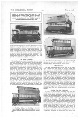
The Hind Platform.
The hind platform of a double-decker, in order to be effective, should be sufficiently long, so that the inside and outside passengers do not get in one another's way. With a modern chassis 3 ft. 6 ins. may be regarded as a minimum and 4 ft. as the desirable dimension. The front edge of the platform is about 1 ft. inside the overall width of the body. Of this 9 ins. represents the width of the step, bringing this within easy reach of the kerb. The back edge of the platform is usually in line with the off-side standing pillar_of the doorway. This gives sufficient width of foundation for fastening the foot of the staircase, and it is not increased unless it is thought necessary to give direct support to the Stairs by a special stanchion. The platform is made up by bolting on a framework of hardwood, upon which the boarding is laid, the wearing slats running transversely. The framework includes intermediates to which the bottom of the staircase is secured. Provision has also to be made for fastening the lower end of the hind fender and staircase stringers for support ing the advertising board (set at an angle so that it catches the eye more readily),• and often the police board on which is screwed the licence plate.
The Staircase.
The most interesting part of the body is the staircase. During the busy hours of the day there may often be three or four passengers mounting at the same time, apart from others standing or walking across the platform. Therefore, a good factor of safety is necessary. This is ensured by using inside and outside stringers of 20-gauge steel, accurately fitted to the treads and risers. The treads are all-important, as they have to bear the weight, whereas the risers are inserted to prevent over-stepping, whilst, incidentally, they help to support the treads. These, being exposed to the weather, should be of elm or pitch-pine, and provided with a pair of tread plates, the front one being let in flush to protect the nosing and the second just laid on to give safe foothold. The treads are supported on a pair of angle irons and the risers are fastened to fillets on each side, both being fastened to the stringers as well.
Setting Out the Staircase.
In setting out the staircase, much has to be done in a small space. If the treads be too wide, the entrance to the lower saloon is impeded, but there will be no difficulty in providing as much width as there is in the central gangway of the lower saloon, say, not less than 1 ft. 3 ins. With a 4-ft. length of platform, a 1-ft. 6-in. tread can be provided. The spiral form, consisting usually entirely of winders, is chosen because it occupies little platform space. The height from the platform to the roof landing is about 6 ft. 5 ins. This, divided equally, gives the height between each pair of treads or the depth of the riser. But before the number of treads is decided upon, the "going," or the length of the space covered by the whole of the treads, must be ascertained, such as is revealed in the plan of the stairs. The greater the going the more room there is for wide treads. The conditions necessary in order to ensure this are a long platform and a large radius to the stringer line, and the bottom riser brought as near to the front edge of the platform as is consistent with safety. Again, the fewer the treads the wider they may be, but this, at the same time, increases the steepness of the flight. Tha top landing follows the camber of the roof so that the height overall of the staircase is reckoned to where the landing is highest on the inner side. if the measurement to the platform be, say, 6 ft. 5l ins., then this can lie set out as eight risers each 9 ins, high and seven treads each of in. The going on the outside stringer will be about 5 ft. 6 ins, and on the inside 3 ft., giving approximately a wedge-shaped tread from 91 ins. to 5f ins. wide. With a good platform length, the going is in proportion, and it will be possible tostarti the stairs well back from the edge of the platform—as much as 2 ft., but with a smaller platform this is often reduced to 1 ft. 6 ins.
The Staircase Rails.
The outer staircase rail is of 1-in. brass tube running parallel with the top line of the stringer and turned at its lower end so as to form a stanchion. This is socketed at the edge of the platform. The main portion of the rail is supported on three stanchions, with a top cross flap of concave section shaped to correspond with the rise Of the rail and a long flap at the foot for fixing to the stringer. These stanchions also provide a support for the staircase band or panel, which acts as a screen as well as for the display of advertisements. The outer rail is about 3 ft. 3 ins, above each step, measuring vertically above the tread.
The inner staircase rail is now usually of the same diameter and material as the outer one. Formerly a thinner and painted one of round Iron was used. The inner rail is flapped to its stringer at the level of the third tread and rises abruptly; almost vertically, passing close to the edge of the hind canopy, where it is again flapped, and then up to the level of the top rail of the roof enclosure. With the wide hind platform there is also a dividing hand pole mounted in the centre of the front edge and fastened to the canopy raid above.
The Top Landing.
The landing on the top must not be restricted, since, unless an upper saloon be provided, this part of the bus Is the most dangerous when the vehicle is moving. Therefore, it is stipulated that there must be at least 2 ft. 2 ins, from the top of the staircase forward to the back of the last off-side seat. There is seldom any need to scamp this dimension, as the length of roof available is always greater than that of the floor of the lower saleon, because a portion of both the front and back canopies can be utilized. The top landing is not flat, owing to the camber of the roof—another reason why there should be space for the passenger to obtain an easy grasp of the rails provided. From this point of view it is an improvement if the staircase can finish by completing a semi-circle at the top, so as to approach the roof parallel with its longitudinal axis. A pair of straight flights with a half-landing offers similar advantages.
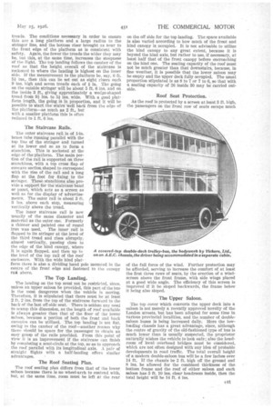
The Roof Seating Plan.
The roof seating plan differs from that of the lower saloon because there is no wheel-arch to contend with, but, at the same time, room must be left at the rear on the off side for the top landing. The space available is also varied according to how much of the front and hind canopy is ,occupied. It is not advisable to utilize the hind canopy to any great extent, because it is beyond the hind axle, but rather to use, if necessary, at least half that of the front canopy before encroaching on the hind one. The seating capacity of the roof must not be Batch greater than that downstairs, because, in fine weather, it is possible that the lower saloon may be empty and the upper deck fully occupied. The usual proportion stipulated is as 8 to 7 or 7 to 6, so that with a seating capacity of 26 inside 30 may be carried outside.
Roof Seat Protection.
As the roof is protected by a screen at least 3 ft. high, the passengers on the front row of seats escape much of the full force of the wind. Further protection may be afforded, serving to increase the comfort of at least the first three rows of seats, by the erection of a windscreen above the front frame, with side wings placed at a good wide angle. The efficiency of this screen is improved if it be sloped backwards, the frame below it being also sloped.
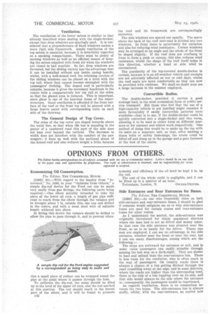
The Upper Saloon.
The top cover which converts the upper deck into a saloon is not merely a recently approved novelty of the London streets, but has been adopted for some time in various provincial localities, and the number of doublesaloon buses is being increased daily. Here the lowloading chassis has a great advantage, since, although the centre of gravity of the old-fashioned type of bus is much lower than is usually suspected, the proprietor naturally wishes the vehicle to look safe; also the headroom of local overhead bridges must be considered, which are not often designed with any idea of probable developments in road traffic. The total overall height of a modern double-saloon bus will be a few inches over 14 ft. If the chassis be 2 ft. high off the ground and 8 ins, be allowed for the combined thickness of the bottom frame and the roof of either saloon and each saloon has 5 ft. 10 ins, clear headroom inside, then the total height will he 14 ft. 4 ins.
Ventilation.
The ventilation of the lower saloon is similar to that already described when dealing with the single-decker, except that drop windows are sparingly used. It is considered that a preponderance of fixed windows makes a more rigid side framework. Ample ventilation of the top saloon is essential, because it is invariably regarded as a smoking compartment. There must be plenty of opening windows as well as an efficient means of keeping the saloon supplied with fresh air when the windows are closed in bad weather. So far, drop windows are favoured, but the sliding variety has the advantage that it can be installed without any inside casing boards, whilst, with a well-domed roof, the retaining catches of the sliding windows can be placed on a level with the top rail, where they cannot become entangled with the passengers' clothing. The domed roof is particularly suitable, because it gives the necessary headroom in the centre with a comparatively low top rail at the sides, so that the glazed area is reduced. This is important, since glass is one of the heaviest items of the superstructure. Good ventilation is afforded if the front surface of the roof or the front top rail be pierced with a large louvre panel with corresponding exits on each side of the doorway.
The General Design of Top Cover.
The sides of the top cover are sloped inwards above the waist line, so that when tire bus is standing in the gutter of a cambered road this part of the side does not lean over beyond the vertical. The decrease in width does not interfere with the comfort of the passengers; it lines up well with the sectional shape of the domed roof and also reduces weight a little, because
the roof and its framework are correspondingly narrower.
The side windows are spaced out equally. The space above the back of the roof surround is divided into two windows. In front there is opportunity for variation and also for reducing wind resistance.Corner windows may be arranged at an angle and the whole of the front be sloped slightly. If the roof does not overhang in front to form a peak or canopy, this also reduces wind resistance, whilst the shape of the roof itself helps in this direction, whether a head or side wind be encountered.
The popularity of the top-covered double-decker is certain, because it is an all-weather vehicle and receipts are not adversely affected on wet or cold days, whilst the roof seats are more comfortable as they can now be provided with cushions. We shall no doubt soon see a large increase in the number employed.
Convertible Bodies.
The double-decker, provided it carries a _good average load, is the most economical form of public service transport. But those who feel that the use of a high-capacity vehicle is not justified might consider it more favourably if easily convertible patterns were available—that is to say, if the double-decker could be quickly converted into a single-decker and vice versa, allowing it to be used in either form on different journeys or for summer and winter work respectively. One method of doing this Would be to make up the top with its seats as a separate unit, so. that, after undoing a dozen bolts or safety fastenings, the whole could be lifted off and slung up in the garage and a gate fastened at the foot of the stairs.