


AUTOMATIC LUBRICATION.
Page 28
If you've noticed an error in this article please click here to report it so we can fix it.
A Résumé of Recently Published Patents.
There are many features of design, the incorporatian of which in the construction of touring cars is most commendable, maybe even essential, but which might Pall for Criticism if applied to commercial motor vehicles, on the ground of extravagance. Such, for example, are eight-cylinder engines, and, to a certain degree, electric starting equipment, and in studying touring car design from the standpoint of the eonmiercial-motor user, as, for example, on such aneocca.sion as the annual November Show at Olympia, one has to make certaixiereservations of
that kind. .
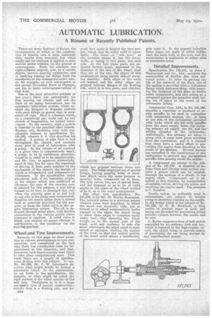
One of the Most, attractive exhibits at last year's .Show was undoubtedly the Guy touring car diesels, and not the . least of its many fascinations was its automatic bibrication system, which enabled the designer to dispense entirely with euch things as grease cups or occasional oil cups. Here is a feature which, on a commercial car, could not, by any stretch of imagination, be termed extravagant. On the contrary, such a system •
is essential in the practical ideal chassis. Readers will, therefore, turn with considerable interest to specification No. 141,245, wherein S. S. Guy describes his method. A system of pipe lines is laid 'throughout the chassis, and connects every part in need of lubrication with a pump. As the volume of ail required in a given time is comparatively entail, a pump, to be in continuous operation, would be so small as to be impracticable, and Mr. Guy, in apparent acknowledgment Of this, has hit upon the expedient of driving it from some member of the mechanism of the chassis; the motion of which is intermittent and comparatively infrequent. In the specification under discussion, and, if we remember aught, in the chassis which was exhibitedat Olympia.: the arm of the steering gear is selected for this purpose, a earn being formed on its boss, so arranged that only when the steering gear is at full lock _ to one .side is the pump ram reciprocated. Supplies are drawn either from a special tank or reservoir provided for the purpose, or from the relief valve in. the en. gine lubricating system. The oil is delivered through metal pipes, with flexible connections to the various points where lubricant is required. A relief valve is fitted, and surplus oil passes through it andIreturns to the crankcase via the steeringagearbox.
Wheel and Tyre Improvements.
Recently on this page we drew attention to current developments in tyre construction, and commented, on the fact that there was considerable room for improvementin this direction, and that, moreover, such improvements were likely to take place comparative lv soon. This week there are a couple of specifications dealing with this subject. In one, No. 141,096, Mr. F. W. Lanchester describes what might briefly he termed a pnemnatic wheel. In the construction,• as set forth in the 'specification, the metallic, or what might he called the rigid portion of the wheel consists of the hub only. Contiguous to it is a large pneumatic tyre of special construction; outside that. is a floating rim, and be
.C54
yond that again ie located the tyre proper, which may be either solid or pneumatic. The inner, or "sub tyre," as the inventor names it, has the cover, wails, or casing in two parts, one each. side. At the hub these parts are_anchored further apart,. measured in the directipn of the axis of the wheel, than they are at the rim, the abject of this arrangement being mainly thettof ensuring stability. Both edges of the walla are beaded, and the outer edges. are gripped between flanges of the floating rim, which is in two partssand clinches
which are gripped between those two parts. The taffiee employed are of special design, having security Italie, or members which serve the same purpose as security bolts, vulcanized on to them. The tyre valves, too, are of special form, and are disposed so as to .lie at right angles to the plane of the wheel instead of in it, as is the usual arrangement. The other tyre specification, No 141,216, ii by 'Mr. W. Worby Beaumont. The inventor refers to a previous patent wherein tyres were described, in which the tread . was -unusually wide, but so formed as to afford comparatively feeble support to the edges, the object being to allow these edges to compress easily under load, thus throwing the whale weight on to the central part of the tread, until any tendency to side slip arose, whereupon the edges acted to some extent as squeegee, clearing the surface of the road, so that the central portion of the tread could obtain a satisfactory
grip upon it. In the present invention these edges 'aremade of softer rubber than the main body of the tyre,. and the construction is applicable to either solidor pneumatic tyres.'
Detailed Detailed Improvements.
Specification No. 141,151, by John 1. Thornycroft and Co.,. Ltd., concerns the construction of flexible disc type universal joints. In order to... veining the life of the material of the discs, one, of the spiders is provided with a cylindrical flange which embraces-them, thus lessening the tendency of the discs to buckle
u nder compression, and also acting as a safeguard against the propeller shaft falling out. of place in the event of the connection failing.
Commercial Cars, Ltd:'' in No. 141,189, describe a vaporizer or producer to enable paraffin to be used in connection
w ith automobile engines, etc. A lamp at one side of the carburetter provided with wicks which are fed with paraffin from the main supply beats the incom• in primary air supply, the jet, and the mixing . chamber of the carburetter. Additionally, this primary air takes in
• alongwith it some inert gases resulting from the combustion, and it 15 claimed . that these have a useful effect in preventing the engine from knocking as the
result of pre-ignition. Several devices are embodied in the construction of this carburetter to prevent any unvapoeized paraffin from passing inside the engine.
A compressed air starter is the subject of No. 141,192. A chamber of annular form and circular cross section contains a, piston which can he coupled, through the medium of a clutch, to the engine shaft. Compressed air is admitted to tbie chamber, .by manipulation of suitable valves, driving the piston and revolving the engine shaft. The patentee is C. Landale.
Needle valves, as ordinarily used in carburetters, are subject to trouble owing to shoulders wearing on the needle. In the design which is the subject of No. 141,222, by Cl. R. Raekham, a long needle of gradual taper is used, and means are provided for preventing actual metallic contact between the needle and its seat.
F.gccles suggests a form of bolt switch controlled by an ordinary lock and key, which is inserted in the high-tension circuit, the object being. to provide meane of preventing the car being started by any unauthorized person.