


• AN INFINITELY VARIABLE SUSPENSION SYSTEM.
Page 30
If you've noticed an error in this article please click here to report it so we can fix it.
A Resume of Recently Published Patents.
MHE INGENIOUS suspension system
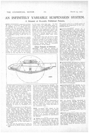
which is described in specification No. 210,821, by A. A, Holle, not only provides for .the, automatic adjustment of the tension of the springs which are stiffened in their action as the speed of the vehicle increases, but also for the practically instantaneous adjustment of eny individual spring while the ear is in motion.
The invention is-described as it might be applied to a chassie_which is equipped 'with semi-elliptic springs fore and aft. Each spring is embraced-at its ends by flat steel resiliPrit plates, the arrangement being such that freedom of movement in a longitudinal direction is
permitted to a limited extent. The springs actually bear on rollers, of which • there are two to each spring, one at each end. The rollers are constrained by • guides to move only in a direction parallel to the top leaf of the spring, and each roller is attached to a, coupling rod, the other end of which is pivoted to the lower end of a plain lever, which is fulcrumed near the middle of its length, and coupled at its other end to the piston of a hydraulic cylinder.
The two rollers of a spring are controlled, in this way, by two pistons, which face one another in a single cylinder, the fluid within which bears equally upon the two pistons. As shown in the accompanying drawing, the pistons are close together, and the rollers as wide apart as possible, being eight at the 'ends of the spring, the flexibility of which .is, therefore, at a maximum.
Increase of pressure of the fluid with in the cylinder will drive the pistons apart, _bringing the rollers closer together, thus decreasing the effective length of the 'spring and stiffening it. By arrenging that the pumps which feed the cylinders are driven,in some way, by the transmission of the vehicle, it is possible to ensure that the pressure in the cylinders and, therefore, also the stiffness of the springs, increase in indirect proportion as the road speed of the vehicle.
It will now be necessary to refer to a feature of the Holle chassis, described 13-16 in this page some time ago. In that chassis there are differential gears to each pair of wheels, one for the off side and one for the near side. The oil pumps for this suspension system are driven off these differential gears, with the result that as the vehicle rounds a corner, the outside 'springs are automatically rendered stiffer than those on the inside.
The pumps draw the oil from a. tank on the dash, and the delivery to each hydraulic cylinder is via a pipe in which is fitted a by-pass, valve. by the matiipulation of which 'the, flexibility of any individual spring may be controlled independently of the others,
Other Patents of Interest.
. GOODS which may be packed in standard size containers can be loaded with ease by the device whieh has been invented by IL E. Spencer, and patented
by him is specification N. 21.0,879. The chassis of a motor lorry is, to all intents and purposes, equipped with a double line of rails, and a detachable ramp embodying rails of the same gauge. The containers for the goods are so made that they will readily slide upon these rails, and the chassis of the lorry is further provided with a couple of winch drums and suitable georing, which may either be hand or power-operated, for hauling the cases up the ramp. In one of the designs illustrated in the specification, the '!rails" are really lines of angle-iron, which carry, at intervals, rollers upon which the skids of the containers rest.
THE two-speed gear fitted to the Atkinson steam wagon is now fairly well known to our readers, and many of them will be interested to learn that the patent for it is new completed and accepted and published in specification No. 211,021.
A FORM of burner for oil fuel, adapt able for steam-wagon use, is described in specification No. 211,014, by Deighton's Patent Flue and Tube Co., Ltd. The oil is led through a jet into a stream of superheated steam and air.
The patent refers to a simple means of regulating the proportions of the combustible enixture --MANUFACTURING pistons by a
simple method, so that. when finished they shall be -slightly elliptical in shape, the major axis of the ellipse being at right angles to the gudgeon pin, is described in specification No. 210,828, by S. Smith and A.-C. Cars, Ltd. The object of making pistons that shape is to reduce the tendency to knock. The piston is first turned to a diameter slightly in excess of the finished size. A screw is then applied, and the pistoe expanded in the direction of the aids of tbe gudgeon pin. This process causes the piston to become elliptical in section, with the major axis of the ellipse parallel to the gudgeon pin. This piston, thus distorted, is then set up in the grinding machine and ground to the required dimensions. The expander is then removed, and the piston contracts in a direction parallel to the gudgeon pin, so that its iinished shape is again elliptical, with the major axis of theellipse at right angles to the pin.
FACILITATING the injection of grease into the intersticts between the leaves : of a-laminated spring is the object of the device deecribed in specification No. 210,892, . by A. ' liesp and others. A U-shaped bracket carries, at one extremity, a Screwed hollow piece, with a chisel edge adapted to enter between two leaves and separate them. At the other, extremity alever is fitted, and this lever is also chisel-edged. The point of the screwedlpiece is first inserted at one side of the spring, and then the lever, by manipulation, is forced into the other side to an extent sufficient to.part the leaves. Grease is then injected through the hollow screwed part.
• SPECIFICATION No. 210,901, by the British Thomson-Houston Co., Ltd., relates to ignition apparatus for twocylinder horizontally opposed .engines equipped with flywheel magnetos, by attaching sparking plugs to the ends of the secondary winding, and insulating the latter from the primary winding. This provides satisfactory 'ignition,. notwithstanding that the fly*heel is running at engine speed.
IN the chassis design described in specification No. 201,951, A. G. Grice arranges a power unit, consisting of engine, clutch and gearbox, immediately forward of the rear axle, with the clutch and gearbox-in front of the engine. The transmission thence is by sprockets and chain to a longitudinal shaft, 'back to the rear axle.
• FIXING mu dguards so that they may
be readily detachable is the feature of the method which is dealt with in specification No. 210,189, by W. Fairclough. Sockets are fixed to the undersides of the guards, and into these sockets the ends of the brackets fit, being secured by wing nuts.. Rattle is prevented by flat, springs which fit between brackets and sockets. _