


Patents Completed.
Page 20
If you've noticed an error in this article please click here to report it so we can fix it.
New Humber Magneto. Saver Friction Clutch. Novel Starting Device.
Copies of complete specifications of the patents published on this page can be obtained from the Sales Branch, Patent Office, Holborn, WIC., at the cost of sixpence for each specification.
J. M. HEWITT AND THE SAVER CLUTCH CO., LTD., No. 13,489, dated 3rd June, 1914.—The object of this invention is to provide a simple construction of clutch mechanism.
The driving member consists of a bar of rectangular section
bored to receive the shaft and keyed on to it. A segmental slipper is mounted on each end of this bar to slide radially into contact with the outer drum or driven member. The slippers are provided with guides to engage the driving bar on both sides, and they are operated by links pivoted in the driving bar and connected to a sleeve on the driving shaft, which sleeve is operated by the striking gear. The operating link bears on its slipper by a wedge-shaped member which is adjustable by a screw placed in an accessible position.
B. Swari, No. 16,990, dated 17th July, 1914.—This specification describes a starting device for motor vehicles.
The two parts of the one-way clutch are normally kept out of engagement by a spring operating between them. The sprocket-wheel can be rotated by means of a lever and chain operated from a rocking-shaft under the control of the driver, whilst a forked striker fixed on a transversely arranged rocking-shaft can impart axial movement to the sprocket-wheel. The rocking-shaft controls, by means of a lever, a pivoted striker which has an approximately vertical movement imparted to it by the lever. By means of the spring shown in the lower part of the diagram, further pressure is prevented from being applied to the sprocket wheel, and when the engine fires back, the momentarily superior back pressure on the coupling enables the spring operating between the two parts thereof to push the sprocket-wheel back axially until the coupling is completely broken, thus imparting no shock to the mechanism.
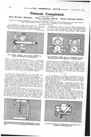
HUMBER, LTD., AND T. A. COLE, No. 1940, dated 24th January, 1914.—This invention relates to an improved construction, of the type of magneto in which the current can be switched to earth when the contact breaker is fully retarded.
The figures show two modifications of the device; in the first the terminal for the attachment of the switch wire is carried by the contact breaker, and this is adapted to make contact with the spring blade when the contact breaker is fully retarded. In the second case, an aim is attached to the centrally arranged terminal, and this again can make contact with the earthing blade. In both cases the blade or its equivalent may be carried by any suitable part of the engine or the frame of the vehicle.
A. W. MANSBRIDGE, No. 18,521, date claimed under the International Convention 17th March, 1914.—In the accompanying drawing is shown an attachment which is screwed into the carburetter so as to assist the starting of an engine in the colder countries.
The attachment comprises a cup-shaped receptacle which opens into the float-chamber of the carburetter, and when applied becomes filled with the petrol contained therein. The receptacle has an insulated lining and contains a heating coil, the terminals of which pass respectively to the upper end and through the bottom of the receptacle.
The attachment is placed in a suitable electric circuit so that when the coil is heated the spirit filling the cup becomes quickly vaporized and passes up in bubbles through the reservoir of petrol, the vapour being trapped by a saucershaped hood carried below the level of the petrol in the float chamber, and overhanging the attachment and fed directly to the mixing chamber through an orifice.