


Layout for a Rear-engined Bus
Page 68
If you've noticed an error in this article please click here to report it so we can fix it.
r-I A DESIGN for the transmission arrangements of a rear-engined bus or coach is given in patent No. 708,871 (Daimler-Benz A.G., StuttgartUntertiirkheim, Germany). The aim is to take the drive from the transversely mounted engine to the axle in such a way as not to interfere with the disposition of other components. The engine crankshaft has a primary acute-angled pair of bevels (1) which take the drive through a large angle. From then .on, a propeller shaft (2) deals with it, the shaft being made in five pieces, all of which are universally jointed, so that it may almost be described as a curved driving shaft. The central member is provided with a bearing (3) mounted on the frame. The patent mentions several advantages of the scheme; they are mostly connected with the favourable layout positions of the fuel tank, the exhaust pipe and other parts.
AN INJECTOR WITH A RUBBER SEAL
AN oil-engine injector in which rubber is employed to form a seal is disclosed in patent No. 708,645 (G. Alric, 7 rue des Bas-Trevois, Troyes [Aube], France). The drawing shows the rubber member (1) which is bonded to the push-rod (2) and an outer sleeve (3). In operation, fuel pressure rising in the interior eventually overcomes the force of the spring (5) and flexes the rubber bush upwards, taking the push-rod with it.
This does not open the needle-vatve immediately, as a short delay occurs while the lostmotion connection (6) is
taken up. The lifting of the needle-valve admits fuel pressure to the underside of its tip, and it is thus given an additional upward force which is added to that of a spring (7). The valve then rapidly ascends, taking up the lost motion in the opposite direction. By the use of the lost-motion coupling, the sluggishness due to the high inertia of the rubber does not affect rapid needle movement.
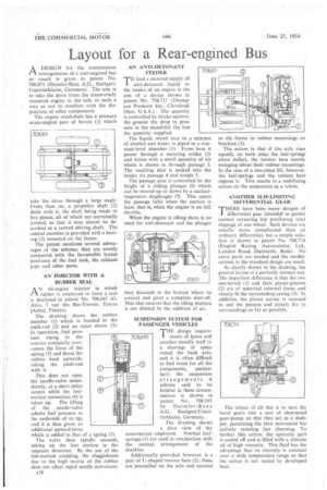
A34 AN ANTI-DETONANT FEEDER
TO feed a metered supply of anti-dctonant liquid to the intake of an engine is the aim of a device shown in patent No. 708,711 (Thompson Products Inc., Cleveland, Ohio, U.S.A.). The quantity is controlled by intake suction; the greater the drop in pressure in the manifold, the less the quantity supplied.
The liquid, which may be a mixture of alcohol and water, is piped to a constant-level chamber (1). From here it passes through a metering orifice (2) and mixes with a small quantity of air which is drawn in through passage 3. The resulting mist is sucked into the intake via passage 4 and nozzle 5. The passage area is controlled by the height of a sliding plunger (6) which can be moved up or down by a suctionresponsive diaphragm (7). This opens the passage fully when the suction is least, that is, when the engine is on full throttle. When the engine is idling there is no need for anti-detonant and the plunger then descends to the bottom where its conical end gives a complete shut-off. This also ensures that the idling mixture is not diluted by the addition of air.
SUSPENSION SYSTEM FOR PASSENGER VEHICLES
THEdesign requirements of loses and coaches usually lead to a shortage of space round the back axle, and it is often difficult to find room for all the components, particularly the suspension arrangements. A scheme said to be helpful in these circumstances is shown in patent No. 708,165 by Daimler-Benz A.G., Stuttgart-Untertilrkheim, Germany. The drawing shows a plan view of the construction employed. Normal leafsprings (I) are used in conjunction with the normal arrangement of the shackles. Additionally provided, however, is a pair of U-shaped torsion bars (2); these are journalled on the axle and secured to the frame in rubber mountings on brackets (3). The action is that if the axle rises equally on both sides the leaf-springs alone deflect, the torsion bars merely swinging about their rubber mountings. In the case of a one-sided lift, however, the leaf-springs and the torsion bars oppose it. This results in a stabilizing action on the suspension as a whole.
ANOTHER SLIP-LIMITING DIFFERENTIAL GEAR THERE have been many designs of I differential gear intended to permit normal cornering but preventing total slippage of one wheel, Such devices arc usually more complicated than an ordinary differential, but a simple solution is shown in patent No. 708,714 (English Racing Automobiles, Ltd., London Road, Dunstable, Beds). No extra parts are needed and the modifications to the standard design are small. As clearly shown in the drawing, the general layout is a perfectly normal one. The important difference is that the two sun-bevels (1) and their planet-pinions (2) are of spherical external form, and closely fit the surrounding casing (3): In addition, the planet carrier is recessed to suit the pinions and closely fits its surroundings as far as possible.
The object of all this is to turn the bevel gears into a sort of obstructed gear-pump, so that they act as a dashpot, permitting the slow movement but actively resisting fast churning. To further this action, the epicyclie part is sealed off and is filled with a silicone oil of high viscosity. This fluid has the advantage that its viscosity is constant over a wide temperature range so that the action is not varied by developed heat.