


Progress in Gear-changing Methods
Page 48
If you've noticed an error in this article please click here to report it so we can fix it.
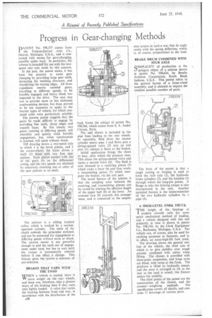
PATENT No. 598,377 comes from the Timken-Detroit , Axle Co., Detroit, Michigan, U.S.A., and is concerned with means for gear-changing, possibly under load. In particular, -the scheme is intended`for use with the tWospeed rear axle made by this concern.
In the past, the patent states, it has been the practice to assist gear changing by providing large gear teeth, increasing the meshing clearance, and chamfering the mating edges. All thqse expedients merely enabled gears, travelling at different speeds, to be forcibly engaged, and heaVy shock was imparted to the drive. The next step was to provide more or less elaborate synchronizing devices, but these proved to be too expensive to apply to the heavier types of vehicle, for which twospeed axles were particularly suitable.
The present patent suggests that the gears be' made ,difficult to engage by providing fine teeth, sharp edges and smooth faces.By this means, two gears, running at differing speeds, will smoothly and quietly resist forcible engagement, but, when synchronism is reached, will mesh without shock.
drawiiig shows a two-speed axle in which 1 is the bevel 'pinion, and 2 the crown-wheel; the -latter drives a shaft (3) fitted with two free spur pinions. Each pinion meshes Ix ith one of the gears (4) on the differential casing, and the two speeds are obtained by selectively clutching one or other of the spur pinions to its shaft.
The selector is .a sliding toothed collar, which is worked by a suctionoperated cylinder. . The teeth of the clutch embody the principles outlined, and can be presented for engagement at differing speeds without noise or shock. The suction motor is not powerful enough to pull the teeth out of engagement under load, but has to wait until the torque is momentarily relieved before it .can effect a • change. This feature gives the system a measure of pre-selection. .
BRAKES THAT VARY WITH _ THE LOAD .
WHEN a vehicle is loaded, there is VV more weight on therear wheels, and these can, therefore, take a greater share .of the braking than if they.were . only lightly loaded. A valve that varies the braking between front and rear, in accordance with the distribution of the
load, forms the subject of patent No. 598,366, which comes from S. A. Andre Citroen, Paris.
The unit shown is included in the pipe lines leading to the rear wheels. In operation', fluid from the master cylinder enters pipe 1 and flows past a siring-opened valve (2) into an exit port (3), whence it flows to the brakes.
Initial application brings the shoes to bear, after which die' pressure rises. This closes the stiring-ottened 'valve and opens a second valve (4): The fluid is now directed to a receiving piston (5) which rocks a lever (6) and thus works a transmitting piston (7) which energizes the brakes, via the exit port.
The novel feature of the scheme is that the coupling ratio between the receiving and transmitting pistons can be varied by altering the effective length of the upper half (8) of the lever. An external arm (9) controls this arrangement, and is connected to the suspen
The basis of the patent is that a single casting or forging is used to form the stub axle (I), the hydraulic brake cylinders (2), and the knuckle (3) through which the king-pin passes. A flange to take the braking torque is also incorporated in the unit. Another patented feature, is the interconnection of the two hydraulic cylinders by a pipe (4).
A HIGH-LEVEL FORK TRUCK
THE height of the fuselage ot modern aircraft calls for some quick mechanical method of loading, and a vehicle designed with this end primarily in view is shown in patent No. 598,539, by the Clark Equipment Co., Buchanan, Michigan, U.S.A. The vehicle can, of course, also be used for stacking purposes in factories, and is, in effect, an extra-high-lift fork truck.
The drawing shows the general outline of the vehicle, the chief aim of which is to give stability over rough ground, combined with safety when lifting. The chassis is provided with three-point suspension, and large tyres are fitted, with twins at the front. The platform is lifted by hydraulic means, and the mast is arranged to tilt to the rear as the load is raised; this feature makes for stability.
The chief points of the patent are the construction of the chassis, and the counter weighting methods. The specification covers all details, and contains 17 drawings of various parts.