Aiding Oil-engine Starting A l)F,VICE introduced in Germany, some time ago,
Page 38

If you've noticed an error in this article please click here to report it so we can fix it.
to eliminate starting difficulties with anti-chwamber oil engines, and which became popular under the name of the Bosch Starting Helper, has recently undergone important alterations, not only to its design but also to the principle on which
1324 't functions. It is now to be marketed as the Bosch Oil Vaporizer, which expression seems to emphasize a decided departure from the original form.
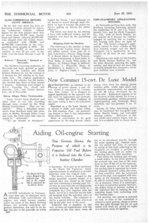
The device, which is flanged to the intake manifold, consists mainly of a vertical tube (a), closed at its lower end and containing a heating pipe (b). As may be seen from the accompanying sectional drawing, the tube leads to a receptacle (a,) and, together with the latter, serves as a reservoir for the leak oil escaping from the injection valve of the fourth cylinder. The container is fed by a special delivery pipe, shown at (d) in the plan view of the cover.
Sufficient fuel is supplied, in thie way, to meet all requirements, with the exception of the first start, when oil has to be introduced directly through the screw opening (g), situated opposite the service fuel inlet. To prevent an excess of fuel from collecting in the receptacle an overflow is provided in the closing plate with an outlet (e) projecting into the inlet manifold.
Fuel enters the heating pipe through a small orifice, in the lower portion of the screwed cap, and rises to the same level as that of the oil in the reservoir. The small quantity of the fuel inside the heating pipe is vaporized by a heating element, mounted within the cover. in close conection with the horizontal part of the pipe, and supplied with electricity at the terminal, clearly shown. It will be noticed that the heating pipe (b) is enclosed, where it is submerged, in a tube of somewhat greater diameter, the object being to prevent cooling of the vaporized fuel by keeping the surrounding liquid from contacting with the heating pipe.
For starting, the current is switched on and, so soon as the crankshaft is rotated a warm gaseous charge is drawn into the inlet through the jet (f) and tidied with fresh air, giving an explo• sive mixture ready for ignition.


