


An Aid to
Page 68
If you've noticed an error in this article please click here to report it so we can fix it.
GEAR CHANGING
A Résumé of Recently Published Patent Specifications.
IN their specification, No. 311,252, the Hurefrey-Sandherg Co., Ltd., and T. B. Barrington describe a device which renders the change from one gear to another easier than with the mechanism usually employed.
It is well known that when a clutch is withdrawn there is, with the ordinary construction, still a member of considerable diameter and appreciable weight left spinning. The momentum of this member, added to that of the gears on the layshaft, causes. the released mechanism to resist any change of speed which it is desired to make by introducing a fresh set of gears into mesh, Efforts have, therefore, been made from time to time to provide a clutch member of small diameter and of light weight. Amongst these attempts perhaps the most successful was the wind-on clutch used on the Mercedes in the early days of the industry; in this the member left spinning was only of a few inches diameter.
The object of the present invention is to provide a member of sufficient diameter to ensure a good take-up of a clutch, yet ,at the same time to isolate this member from its shaft when the clutch is released. With this in view, in the present instance a second clutch is provided which is situated in the centre of an ordinary plate clutch, and which will automatically free itself from the main clutch when the latter is withdrawn. The second device described is of the well-known •type bearing the name of Liumfrey-Sandberg, where rollers Net at a slight angle to the axial line of the shaft impinge on conical members, thus forming a unidirectional drive. In this type of one-way clutch a slight lateral movement of one member in relation to the other will prevent the rollers from jamming on the conical faces, so by slightly moving the outer member (A) to the left the second clutch is released so that the spinning effect of the large disc does not influence the shaft to which it is usually rigidly connected.
The arrangement shown would appear to provide a unidirectional drive in the second clutch at all times, but we understand that further improvements are in hand which will provide a hi-directional drive at this point.
• Machining Tapered Serrated Holes.
THE making of tapered boles which have serrations inside them to mesh with similar serrations on the shaft on which articles such as levers are to be fixed has always been considered a difficult process, as no very satisfactory method has as yet been designed for the formation of such holes. The specification, No. 311,296, of E. G. Matravers and-the Adamant Engineering Co., Ltd., of Luton, dose ri b es a new • method of producing such holes.
It is well known that parallel holes with internal serrations can be easily made in a machine for the purpose by the ordinary process of drawing a broach through the holes. Tbe method new described consists of first forming the hole parallel and serrating it by the above-mentioned method, then forcing' into the hole a taper serrated drift so that the material will be pressed out to the required taper. It is not very clear how the metal can be 'made to yield to the taper usually employed in such holes, as no mention is made of the metal being hot while the tapering is being produced.
More Perpetual-motion Machinery.
UNDER the title of "A Self-driving Gravity Motor," T. R. Leslie, of Perth, described in specification No. 311,478 a device in which falling weights not only lift other c46 . . . •
weights of the same value, but in some way, whieh he does not clearly explain, will have some energy to spare for other purposes. The arrangement bears a close resemblance to the device invented by a Marquis of Worcester, the fallacy of which is one of the first things learned by a. student of mechanics.
The desire to get "something for nothing '.' can be easily understood when we learn that the " invention " comes from Scotland ; we thought, however, that technical education in that land was on a higher plane. It appears to us to be a pity that the inventor did, not make a working model before filing his specification and thus helping to choke up the Patent Office with useless labour-wasting efforts! We feel sure that we are right in surmising that he has not made a "working" model, as if he had done so he would have found out the fallacy of his idea in time to prevent further effort in this direction.
A Friction-clutch Starter.
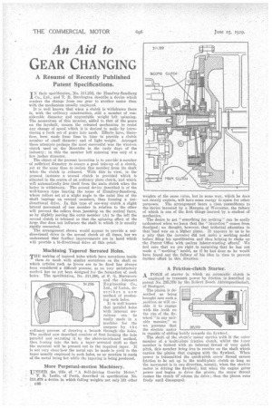
A FORM of starter in which an automatic clutch is employed to transmit power by friction is described in patent No. 285,370 by the Robert Bosch Akteingesellschaft, of Stuttgart.
The pinion is described as being brought into sueli position as will enable it to engage with the teeth on the rim of the flywheel "in any suitnble manner," so we presume that the electric motor is capable of sliding bodily towards the flywheel,
The shaft of the electric motor carries with it the outer member of a multi-plate friction clutch, whilst the inner member is formed with an internal thread of very quick pitch, this member being free to revolve on the shaft which carries the pinion that engages with the flywheel. When power is transmitted the quick-pitch screw thread causes friction to be set up in the multi-plate clutch so long as the movement is in one direction, namely, when the electric motor is driving the flywheel; but when the engine gains power and begins to drive the pinion, the screw thread causes the clutch fii' release its' drive ;thus the pinion runs freely until disengaged.
.. .