


An Electrically Heated Carburetter
Page 53
If you've noticed an error in this article please click here to report it so we can fix it.
AMONGST the multitude of devices for using fuels other than ixtrol which have been developed on the Continent during recent years one of the most interesting appliances we have yet examined is an Italian invention, the S.B. Tarbumtter. This is unusually
simple and compact in design and • incorporates an electrically heated vaporizing chamber, the heat being employed when heavy fuels such as gas oil, naphtha, etC., are to be used in the engine. One of the strong features of the " S.B." is the fact that when the electric heater is switched off petrol may be used without any need for alteration or adjustment of the carburetter.
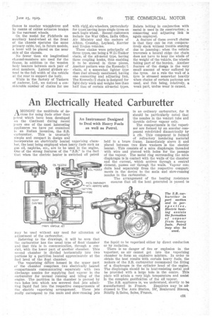
Referring to the drawings, it will be seen that the carburetter has the usual type of float 'chamber and that this is in communication, :through a conduit, with the lower part of another chamber. This second chamber is divided horizontally into two portions by a partition located approximately at the fuel level of the' float chamber.
The vaporizing dgirice housed in the upper part of the chamber comprises two electrically heated compartments communicating Separately with two discharge nozzles for supplying fuel vapour in the carburetter for normal running and idling of the engine. The partition in the chamber is pierced by two holes into which are screwed fuel jets admitting liquid' fuel into the respective compartments of the electric Vaporizing arrangement. These jets really correspond tothe mein and slow-running jets . . in an ordinary carburetter, for it should be particularly noted that the nozzles in the venturi tube and throttle deliver vapour only.
The compartments in the vaporizer are formed by an annular component subdivided diametrically by a rib. This component is formed of refractory insulating material held in a brass frame. Immediately, above it and placed between two fibre washers is the electric heater. This consists of a mica diaphragm threaded with wire and pierced with holes for the passage of the vapour. The metal ring surrounding the mica diaphragm lain contact with the walls of the chamber and the current, which arrives through a central element, passes out through the walls. Vapour con nuts lead separately from the respective compart-, ments in the device to the main and slow-running nozzles in the carburetter.
The arrangement of the heating resistance ensures that all the heat generated is passed to the liquid to be vaporized either by direct conduction or by radiation.
There is no danger of fire or explosion in the vaporizer, as air cannot get into the vaporizing chamber to form an explosive mixture. In order to obtain the best results with certain heavy fuels, the makers of the S.B. carburetter recommend the fitting of a diaphragm in the cylinder head of the engine. The diaphragm should be in heat-resisting metal and be provided with a large hole in the centre. This plate will attain a very high temperature and assist in the complete gasification of the oil 'vapour.
The S.B. appliance is, we understand, shortly to be
manufactured in France. Enquiries may be addressed to The Auto Station, 18f, Boulevard Einem]. S/Seine, Seine, France.