


A Novel Rigid SIX-WHEELED TRAILER
Page 52
Page 53
If you've noticed an error in this article please click here to report it so we can fix it.
VOLLOWING upon the great
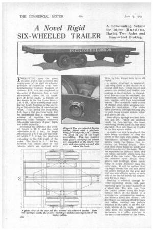
success which has attended the employment of the rigid six-wheeler principle in -connection with commercial-motor vehicles, Taskers of Andover, Ltd., has just completed to the order of Pickfords, Ltd., a rigid six-wheeled -trailer for the transPort of 10-ton loads. A feature of the design is the low frame level2 ft. 6 ins.—thus allowing easy loading for heavy burdens, or the carrying of lift-van bodies of considerable depth. The model for Pickfords, Ltd., has a fiat platform body, but we understand that a considerable number of inquiries has . been received from furniture removers who desire containers of great depth and cubic capacity.
Excluding the drawbar, the overall length is 16 ft. and the total wheelbase 9 ft. 2 ins.; the bogie ..wheelbase is 2 ft. 6 ins, and the overall width 7 ft. 3 ins., the platform extending to the full length of the axles. The track is 5 ft. 10 ins, between the centre lines of the wheels, which are equipped with 22-in. by 5-in. Poppe twin tyres all round.
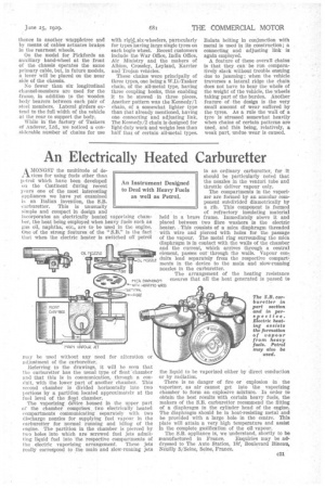
A spring drawbar is employed, this being fixed to the chassis on a lateral pivot bar. Cross-braces and gussets are riveted and welded into position on the drawbar. A channelsteel fore-carriage is employed, the framework consisting of four members, together with four longitudinal braces. The turntable frame is also of channel steel, with adequate provision for lubrication. The brake cable passes up through the king pm, its path being around rollers, below and above the pm.
Semi-elliptic springs are used both fore and aft. They are mounted inside the fore-carriage, the front • ends being pivoted and the rear ends sh*ckled ; they are fixed by U-bolts to the two square axles.
A single rear axle is employed, the ends being machined to form the pivots of the bogie side plates. The semi-elliptic springs are almost hidden inside the frame, thus re, ducing the loading height. Oneinch steel plates form the inside and outside members of the bogie. These are separated by distance tubes, and the whole assembly pivots upon the ends of the rear axle. The wheels are mounted upon Skefko deepgroove ball bearings, those inside being of larger diameter than the outer ones. It will be realized that the bogie wheels rise and fall about the centre formed by the axle and that one semi-elliptic spring on each side of the trailer forms the suspenEion for each bogie.
Braking is effected through internal-expanding shoes, each pair operating upon the inner diameter of + a wheel rim. Tile wire rope from the tractor passes along the longitudinal centre of the trailer to a whippie-tree compensating mechanism midway Wong the chassis; this distributes the braking effort through two cables, running over pulleys attached to the axle, to the two forward. wheels of the bogie. Anther cable from the compensator runs backwards to a Pulley attached to the rear cross-member of the frame,
thence to another whippletree and by means of cables actuates brakeS in the rearmost wheels.
On the model for Pickfords an auxiliary hand-wheel at the front of the chassis operates the same primary cable, but, in future models, a lever will be placed on the near side of the chassis.
No fewer than six longitudinal channel-members are used for the frame, in addition to the wooden • body bearers between each pair of steel members. Lateral girders extend to the full width of the vehicle at the rear to support the body.
While in the factory of Taskers of Andover, Ltd., we noticed a con. siderable number of chains for use with rigid_ six-wheelers, particularly for types having large single tyres on each bogie wheel. Recent customers include the War Office, India Office, Air Ministry and the makers of Albion, Crossley, Leyland, Karrier and Trojan vehicles.
These chains were principally of three types, one being a W.D.-Tasker chain, of the all-metal type, having three coupling hooks, thus enabling it to be stowed in three pieces. Another pattern was the Kennedy/1 chain, of a somewhat lighter type than that already mentioned, having one connecting and adjusting link. The Kennedy/2 chain is designed for light-duty work and weighs less than half that of certain all-metal types. Balata belting in conjunction with metal is used in its construction; a connecting and adjusting link is again employed.
A feature of these overall chains is that they can• be run comparatively slack without trouble ensuing due to jamming; when the vehicle traverses a lateral ridge the chain does not have to bear the whole of the weight of the vehicle, the wheels taking part of the burden. Another feature of the design is the very small amount of wear suffered by the tyres. As a rule the wall of a tyre is stressed somewhat heavily when chains of certain patterns are used, and this being, relatively, a weak part, undue wear is caused.