


Patents Completed.
Page 32
If you've noticed an error in this article please click here to report it so we can fix it.
Pneumatic Wheel. Preventing Valve-stem Leakage. Vickers' Piston-rings.
A. SANG, No. 342, dated 6th January, 1914.—The wheel described in this specification has an air tube carried. in a channel-shaped rim, which is supported by the spokes. The air tithe is enclosed in an inexteneible casing of canvas so that it can yield under pressure but is prevented from expanding. Between the channelled rim and the air tube is an inner
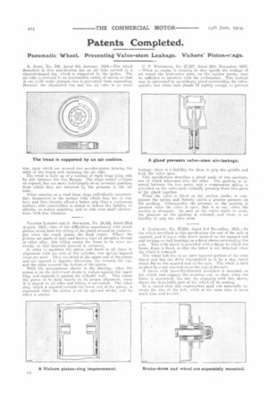
run, upon which are secured two annular-plates forming the sides of the treads and enclosing the air tube.
The tread is built up of a number of rigid rings lying side by side between the two flanges. The rings cannot collapse or expand, but can move individually to an eccentric position, from which they are returned by the pressure in the air tube.
When running on a road these rings individually accommodate themselves to the surface with whieh they are in contact, and they thereby afford a better grip than a continuous surface; this construction is stated to reduce the liability to sideslip, to reduce splashing, and to ride over small obstructions with less vibration.
VICKERS Lim= and G. 13ounceett, No. 19,185, dated 23rd August, 1913.—One of the difficulties experienced with trunk pistons arises from the tilting of the piston. around its gudgeonpin when the crank passes the dead centre. Where the pistons are made of steel and have a liner of phosphor bronze or other alloy, this tilting causes the liners to be worn unevenly, so that frequent renewal is necessary. In order to maintain the piston and liner& at all times in alignment with the axis of the cylinder, two special tapered rings are titer]. They ale fitted at the upper end of the piston and are tapered in opposite directions, one towards the top, and the other towards the bottom of the piston.
With the arrangement, shown in the drawing, when the piston is on the downward stroke it wedges against the upper
ring, and expands it against the tylinder wall. This causes the piston to be held exactly in its proper alignment, since it is stayed on all sides and tilting is prevented. The other ring. which is tapered towards the lower end of the piston, is expanded when the piston is on its upeeeed stroke, and its effect is similar. C. F. WEsTeuttr, Nn. 27,527, dated 29th November, 1913_ —When an engine is running at slow speeds the leakage of air round the inlet-valve stem, on the suction stroke, may be sufficient to interfere with the carburation. This leakage may be prevented by an ordinary gland surrounding the valvespindle, but when such glands fit tightly enough to prevent leakage, there is a liability for them to grip the spindle and hold the valve open.
This specification describes a gland made of two portions, one of which telescopes into the other. The packing is inserted between the two parts, and a compression spring is provided on the valve-stem normally pressing there two parts of the gland together.
When the valve is lifted on the suction stroke, it compresses the spring and thereby exerts a greater pressure on the packing. Consequently the pressure on the packing is greatest when the valve is open, that is to say, when the suction is strongest. As soon as the valve starts to close, the pressure on the packing is released, and there is no liability to grip the valve stem.
E. ILSEMANN, No. 27,834, dated 3rd December, 1913.-111 the wheel described in this specification the end of the axle is squared, and it has a wide sleeve secured on the squared end and turning on hall bearings ou a fixed sleeve surrounding the axle. This wide sleeve is provided with a flange to which the braise drum is fixed, so that the latter is not detached when the wheel is removed.
The wheel hub fits on an outer tapered portion of the wide sleeve and has the drive transmitted to it by a dog clutch which fits on the squared end of the axle. The whole is held in place by a nut screwed on to the end el the axle.
A sleeve with inwardly-directed shoulders is mounted ea the clutch and engages the securing nut, so that, when the latter is unscrewed, the nut, by engaging with this sleeve, draws the detachable part of the wheel off its seating.
It is stated that this construction need not materially increase the size of the hub, while at the same time it saves much time arid trouble,