


Patents Completed.
Page 18
If you've noticed an error in this article please click here to report it so we can fix it.
LUBRICATOR.—Ifunsber, Limited and Another.—No. 24,081, dated 31st October, I907.—This invention relates to force-feed lubricators of that type in which a rotary pump forces the oil through a sight-Teed
t. tube. The rotary pu (K) draws oil from a reservoir (A) a •;forces it through a channel to the sig -feed tube (C). In order to avoid excessive pressure in the sight-feed tube (C), the pump (K) is provided with a movable wall (N) held in position by a spring-pressed plunger (13). When the pressure in the pump becomes excessive, the wall (N) will be moved outwardly against the action of the spring (1") and thus uncover a by-pass (0) by means of which the excessive oil is returned to the tank (A).
CHANGE-SPEED GEAR. —Phillips and Another.—No. 16,961, dated 24th July, I907.—This invention relates to changespeed gearing, and has for its object to provide means whereby the driven shaft takes up .a more gradual connection with the driving shaft at all speeds, Rigidly connected to the driven shaft is one of the members (4) of the dog clutch, and also the hollow, spring, cone member (8) of the friction clutch. The driving shaft carries the other member (12) of the dog clutch, and also the cone member (9) of the friction clutch. This cone member is
integral with a collar (17) which is mounted on the driving shaft (1), and is adapted to be moved along the shaft into engagement with the spring cone member (8). It will be seen that the cone member (9) will first engage the spring cone member (8) and then, on being further advanced, the ,jaws (12) of the dog clutch will engage the jaws (4), and ±hus a positive drive will be obtained. In order to obviate the necessity for maintaining hand pressure on the gear-change lever until the dogs are in engagement, the lever (38) is loosely mounted on a selector shaft (39) carrying a lever (40) which operates the clutches. This selector shaft is provided With •a slot (41) which engages one end of a el* steel spring (42) while the other end of the spring is connected to the lever (38) by a clamp (43). By this means the lever (38) may he moved over CO any desired notch in the quadrant (44), whether the dogs (4, 12) have been moved into engagement or not.
SUSPENSION ARRANGEMENT.Hopper.—No. 19,965, dated 6th September, 1907.—This invention relates to means whereby the body of a vehicle is suspended from the chassis. The chassis (X) is provided with brackets (s) to which bell-crank levers (A) are pivoted, two on
each side as shown. The upper ends of the levers are attached to the main frame of the body (Y) by means of links (al) whilst the lower arms are controlled by compression springs. These springs are interposed between the fixed tubes (b) and the rods (b2) in such a manner that shocks will be transmitted through the springs to the frame of the body.
MOTOR FIRE ENGINE., Merryweather—No. 529, dated 9th January, 1908.—This invention relates to motor vehicles carrying a pump or fire escape, and it provides a shaft placed in line with the engine shaft in such a manner that the pump may be operated by the propelling engine without the intervention of the change-speed gear. The change-speed box (F) contains a part of the engine shaft (Q) and in line with this shaft is a tail shaft (0). One of the members (El of a dog clutch is mounted on this tail shaft, whilst the other member (M) is carried by the engine shaft (Q). The cardan shaft, which is driven by the tail shaft through the universal joint (D), carries a pinion gearing with the spur wheel ,(A) on the pump.
CARBURETTER. — Sargeant. — No. 9,273, dated 22nd April, 1907.—This invention relates to improvements in apparatus for the vaporisation of petrol, and other hydrocarbons, wherein air is circulated between frames supporting sponges, or other absorbent materials, or between sheets of wood which may enclose a layer of black oxide of manganese immersed in liquid hydrocarbon. The apparatus comprises a container (A) having an air inlet (a) and outlet (0). The inlet and outlet are controlled by a slide-valve (D). Arranged within the container are a series of grids (B), the holes in which contain a chemical paste. Pivoted at the inlet end of the container is a shutter (E) which is provided with a series of holes (e) forming air leads to distribute the incoming air over the surfaces of the grids and the
liquid in the container. This 'shutter is supported by a float (F) so that it adjusts itself to the varying level of the liquid.
The paste contained by the grids (B), when in contact with the liquid in the container, assists in the process of vaporisation.
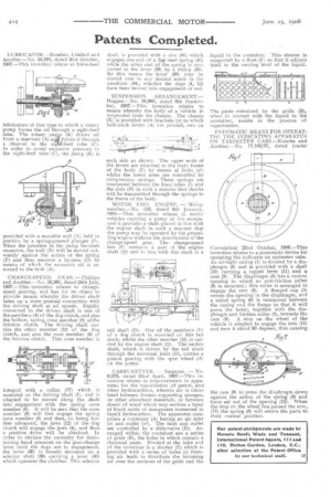
PNEUMATIC MEANS FOR OPERATING THE INDICATING APPARATUS ON TAXIMETER CABS.—Knoche and Another.—No. 17,162/07, dated (under Convention) 22nd October, 1906.—Thie invention relates to a pneumatic device for operating the indicator on taximeter cabs. An air-tight casing (1) is divided by a diaphragm (3) and is provided with a shaft (10) carrying a tappet lever (11) and ai cam (9). The diaphragm (3) has a central opening in which an anti-friction roller (8) is mounted ; this roller is arranged to engage the cam (9). A flanged cap (5) covers the opening in the diaphragm, and a spiral spring (6) is interposed between the casing and the flange so that it will press the latter, together with the diaphragm and friction roller (8), towards the cam (9). A stop on the wheel of the. vehicle is adapted to engage the arm (11) and turn it about 90 degrees, thus causing
the cans (9) to press the diaphragm down against the action of the spring (6) and force air out of the opening (12). When the stop on the wheel has passed the arm,. (II) the spring (6) will returm the parts to. their normal: position.