


Injection Pump for Small Engines
Page 58
If you've noticed an error in this article please click here to report it so we can fix it.
AN injection pump intended for small high-speed engines _is shown in patent No. 662,198, by the American Bosch Corporation, Springfield,0Mass., U.S.A. Operating on an unusual principle. the pump is a compact unit, containing its fuel-lifting 'pump and its governor.
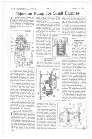
The drawing shows a pump designed for a six-cylindered engine, but only a single plunger is used. This is lifted by a three-lobed cam (1) and returned by a spring (2). In addition to the reciprocating movement, the plunger also rotates, being driven by a train of gears from the camshaft, terminating in gear 3.
In the drawing, the plunger is shorn at the top of its stroke, having forced a charge of fuel past the non-return valve (4). The fuel then travels through port 5 into an annular groove in the plunger. A distributing port (6) connects with the groove, and as the plunger revolves, fuel is led to each of the outlets (7) in turn. Quantity control is achieved by opening spill passages in the plunger at a variable point.
The control member is a close-fitting collar (8) which uncovers the spill ports in the plunger as it ascends. The height of the collar is varied by an eccentric pin on a spindle (9) to which the control rodwork (10) is attached.
A DURABLE HEATER PLUG
TO facilitate the starting of indirect injection oil engines, it is common practice to provide a lieater-plug in the pre-combustion chamber. Such plugs usually consist of a stout filament• which is heated to incandescence by the vehicle batteries. It will be appreciated that once the engine is running, the high combustion temperature will have a destructive effect on the wire filament, and..:on this account its life. is usually short. To. improve matters in this
A40 " respect is the aim of, an improved plug shown in patent No. 659,912, by the Caterpillar Tractor Co., San Leandro, California, U.S.A.
It is proposed to house the filament (I) in a metal cap (2) which completely seals it off from the flame, but is thin enough to become red-hot when the filament is switched on. The wire is coiled, and expands into tight contact with the cap, thus giving good heat conduction.
A thin sleeve (3) of mica is interposed for insulation purposes, and the spare space is filled with powdered aluminium oxide. The coil can he wound to take the full battery voltage; this is more reliable than the usual method of having several 2-volt heaters in series. With the series arrangement, the failure of one plug, of course, affects all the others.
AN INJECTION-PUMP GOVERNOR T°give better control of an oilengine is the object of an injectionpump governor shown in patent No. 662,444, by Robert Bosch Stuttgart, Germany. The operative factor is the degree of suction existing in the air intake.
The drawing shows that part of the pump in which the governor is housed. A chamber (1) is connected to the intake suction,, which works a flexible diaphragm (2) against the force of a spring (1). The diaphragm is attached to the rack-rod (4) of the pump in such manner that an increase in suction tends to cut down the fuel supply. A manually operated double armed lever (5) has three positions; to_ the right it cuts off. the. supply of fuel. the central prisition-gives normal governor control, and to the left excess fuel is injected for start-. jug. To place the lever in the last position,/a powerful spring (6) has 19 be overcome.
A feature of thepatent is the means for coupling the diaphragm to the rack rod; this is not a positive coupling but is permitted a small degree of resilience due to the inclusion-of a spring (7). The object of this is to offset the unde-' sirable increase kt.f. pumping efficiency that occurs at high engine speeds.
TORSION-BAR SUSPENSION
FROM Morris Motors, Ltd., Cowley, Oxford, comes patent No. 662,538, ' describing the suspension system of a frameless v e hi cl e, with particular reference to that of the front wheels. In such a vehicle, the sheet-metal floor, to which all the cotnponents are attached, is liable to be sensitive to high-frequency road shocks, such as those caused by running over
cobble stones. These vibrations are well inside the audible range and are liable to set up an unbearable drumming sound in the vehicle. To avoid this is the object of the layout.
The plan view in the drawing shows a triangular sub-frame (1) on which the engine is mounted via a pair of rubber blocks (2) at the front and a single one (3) at lite rear. The parallel-link suspension is carried on the sub-frame, the torsion bars (4) of which are anchored on a rearward extension (5). The body is attached at four points (6 and 7) using rubber-bushed connections.
The engine receives the highfrequency road shocks directly from the, suspension, and being a heavy mass converts them into vibrations having a frequency below the audible limit.
To accommodate the relative motion which occurs between the body structure and the sub-frame, the steering column has to be provided with a oliding joint.