


A Starter for Large Engines
Page 44
If you've noticed an error in this article please click here to report it so we can fix it.
A Resume' of Recently Published Patent Specifications
A STARTING unit designed prim
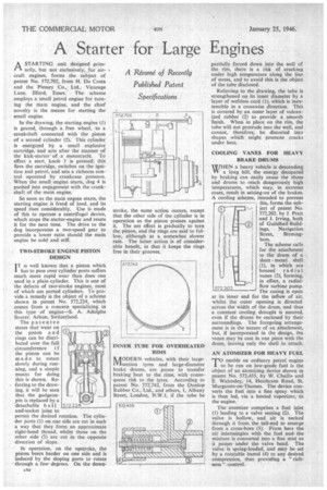
arily, but not exclusively, for air. craft engines, forms the subject of patent No. 572,702, from H. Da Costa and the Plessey Co., Ltd., Vicarage Lane, Ilford, Essex. The scheme employs a small petrol engine for turning the main engine, and the chief novelty is the means for starting the small engine.
In the drawing, the starting engine (I) is geared, through a free wheel, to a crankshaft connected with the piston of a second cylinder (2), This cylinder is energized by a small explosive cartridge, and acts after the manner of the kick-starter of a motorcycle. To effect a start, knob 3 is pressed; this fires the cartridge, switches on the ignition and petrol, and sets a richness control operated by crankcase pressure. When the small engine starts, dog 4 is pushed into engagement with the crankshaft of the main engine.
So soon as the main engine starts, the starting engine is freed of load, and its speed rises considerably. Use is made of this to operate a centrifugal device, which stops the starter-engine and resets it for the next time. The drive to the dog incorporates a two-speed gear to provide a lower ratio should the main engine be cold and stiff.
, TWO-STROKE ENGINE PISTON DESIGN is well known that a piston which has to pass over cylinder ports suffers much more rapid wear than does one used in a plain cylinder. This is one of the defects of two-stroke engines, most of which use ported cylinders. To pro vide a remedy is the object of a scheme shown in patent No. 572,224, which comes from a concern specializing in this type of engine—S. A. Adolphe Snorer, Arbon, Switzerland.
The patentee states that wear on the piston a n d rings can be distributed over the full circumference if the piston can be made to rotate slowly during running, and a simple means for doing this is shown, Referring to the drawing, it will be seen that the gudgeonpin is replaced by a detachable ball and-socket joint to permit the desired rotation. The cylinder ports (1) on one side are cut in such a way that they form an approximate right-hand thread, whilst those on the Other side (2) are cut in the opposite direction of slope.
In operation, on the upstroke, the piston bears harder on one side and is induced by the sloping ports to rotate through a few degrees. On the down
stroke, the same action occurs, except that the other side of the cylinder is in operation as the piston presses against it. The net effect is gradually to turn the piston, and the rings are said to follow, although at a somewhat slower rate. The latter action is of considerable benefit, in that it keeps the rings free in their grooves.
INNER TUBE FOR OVERHEATED RIMS ' IVIDDERN vehicles, with their largePasection tyres and large-diameter brake drums, are prone to transfer braking heat to the rims, with consequent risk to the tyres. According to patent No. 572,742, from the Dunlop Rubber Co., Ltd., and others, 1, Albany Street, London, N.W.I, if the tube be partially forced down into the well of the rim, there is a risk of . cracking under high temperature along the line of stress, and to avoid this is the object of the tube disclosed.
Referring to the drawing, the tube is strengthened on its inner diameter by a layer of weftless cord (I), which is inextensible in a crosswise direction. This is covered by an outer layer of vulcanized rubber (2) to provide a smooth finish. When in place on the rim, the tube will not protrude into the well, and cannot, therefore, be distorted into shapes which might promote cracks under heat.
COOLING VANES FOR HEAVY BRAKE DRUMS [WHEN a heavy vehicle is descending VI a long hill, the energy dissipated by braking can easily cause the shoes and drums to reach dangerously high temperatures, which may, in extreme cases, result in seizing-on of the brakes. A cooling scheme, intended to prevent Ibis, forms the subject of patent No. 572,202. by I. Pratt and 1. Irving, both of Guildhall Buildings, Navigation
Street, Birmingham.
The scheme calls for the attachment to the drum of a sheet metal shell 11), in which are housed radial vanes (2), forming, in effect, a radial ,
572.2,02 flow turbine pump.
The casing is open at its inner end for the inflow of air, whilst the outer opening is directed across the width of the drum, and thus a constant cooling draught is assured, even if the drums be enclosed by their surroundings. The foregoing arrangement is in the nature of an attachment, but, if incorporated in the design, the vanes may be cast in one piece with the drum, leaving only the shell to attach.
AN ATOMIZER FOR HEAVY FUEL
TO enable an ordinary petrol engine to be run on low-grade fuel is the object of an atomizing device shown in patent No. 572,435, by W. Challis and E. Walmsley, 14, Heathcote Rind, St. Margarets-on-Thames. The device converts the fuel into a fine spray which is then led, via a heated vaporizer, to the engine.
The atomizer comprises a fuel inlet (I) leading to a valve seating (2). The valve is hollow, and air is sucked through it from the tail-end to emerge from a cross-bore (3). From here the air intermingles with the fuel and the mixture is converted into a fine mist as it passes under the valve head. The valve is spring-loaded, and may be set by a rotatable barrel (4) to any desired compression, thus providing a " richness " control.