


A STAND-BY FOR STEAM BRAKES.
Page 70
If you've noticed an error in this article please click here to report it so we can fix it.
A Résumé of Recently Published Patent Specifications.
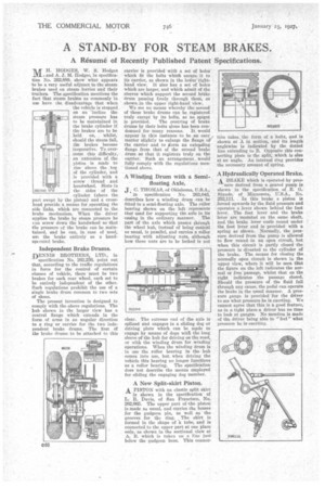
-iur H. HODGES, W. S. Hodges n and A. J. M. Hodges, in specification No. 262,889, show what appears , to be a very useful adjunct to the steam brakes used on steam lorries and their trailers. The specification mentions the fact that steam brakes as commonly in use have the disadvantage that when the vehicle is stopped on an incline the steam pressure has to be maintained in the brake cylinder if the brakes are to be held on, whilst, should the steam fail, _the brakes become inoperative. To.overcome this difficulty, an extension of the piston is made to rise above the .top of the cylinder, and is provided with a screw thread and handwheel. Slots in the sides of the
cylinder (above the part swept by the piston) and a crosshead provide a means for operating the side links, which are connected to the brake mechanism. When the driver nppliee the brake by steam pressure he can screw down the handwheel so that the pressure of the brake can be maintained, and he can, in case of need, us...; the brake entirely as a bandoperated brake.
Independent Brake Drums.
DENNIS BROTHERS, LTD., in specification No. 262,236, point out that, according to the traffic regulations in force for the control of certain classes of vehicle, there must be two brakes for each rear wheel, each set to be entirely independent of the other. Such regulations prohibit the use of a single brake drum common to two sets of floes.
The present invention is designed to comply with the above regulations. The hub shown in the larger view has a central flange which exteuds in the form of arms in an angular direction to a ring or carrier for the two independent brake drums. The first of the brake drums to be attached to this carrier is provided with a set of holes" which fit the bolts which secure it to its carrier, as shown in the loWer righthand view. It also has a set of holes which are larger, and which admit of the sleeves which support the second Hake drum passing freely through them, as shown in the upper right-hand view.
We see no means whereby the second of these brake drums can be registered truly except by its bolts, as no spigot is provided. The centring of brake drums by their bolts alone has been condemned for many reasons. It would appear in this instance to be an easy matter slightly to enlarge the flange of the carrier and to /form an extending flange from that of the second brake drum so that it registers truly on the carrier. Such an arrangement . would fully comply with the regulations mentioned above.
A Winding Drum with a Semifloating Axle, J. C. THOMAS, of Oklahoma, U.S.A., in specification No. 263,043, describes how a winding drum canbe fitted to a semi-floating axle. The roller bearing shown on the left represents that used for supporting the axle in its casing in the ordinary manner. The part of the axle which passes through the wheel hub, instead of being conical as usual, is panallel, and carries a roller hearing with adjusting nuts, although how these nuts are to be locked is not
clear. The extreme end of the axle is splined and engages in a sliding dog or driving plate which can be inede to engage by means of dogs with the long sleeve of the hub for driving on the road, or with the winding drum for winding operations. When the winding drum is in use the roller bearing in the hub comes into use, but when driving the vehicle this bearing no longer functions as a roller bearing. The specification does not describe the means employed for sliding the engaging dog member.
A New Split-skirt Piston.
A PISTON with an elastic split skirt is shown in the specification of L. R. Davis, of San Francisco, No. 262,665. The upper part of the piston is made as usual, and carries the bosses for the gudgeon pin, as well as the grooves for the ring. The skirt is formed in the shape of a tube, and is connected to the upper part at one Place only, as shown in the sectional view at A, B. which is tukeu on a line just below the gudgeon boss. This connee
tion takes., the form of a helix, and is shown at A in section, and its length anglewise is indicated by the dotted line extending to B. Opposite this connecting piece is the split, which is also at an angle. An internal ring provides the necessary amount of spring.
A Hydraulically Operated Brake.
A BRAK1o. which is operated by pres
sure derived from a geared pump is shown in the specification of E. G. Stautle, of Minnesota, TJ.S.A., No. 252,111. . In this brake a piston is forced upwards by the fluid pressure and operates a lever shown behind the foot lever. The foot lever and the brake lever are mounted on the same shaft, and the brake lever curls round under the foot lever and is provided with a spring as shown. Normally, the pressure derived from the pump is allowed to flow round-in an open circuit, but when this circuit is partly dosed the pressure is diverted to the cylinder of the brake. The means for closing the normally open circuit is shown in the upper view, where it will be seen that the figure on the left indicates the normal or free passage, whilst that on the right indicates the passage closed. Should the pressure of the fluid fail through any cause, the pedal can operate the brake in the usual manner. A pressure gauge is provided for the driver to see what pressure he is exerting. We cannot agree that this is a good feature, as in a tight place a driver has no time to look at gauges. No mention is made of the driver being able to "feel" what pressure he is exerting.