


MAKING BRAKE APPLICAT EASIER FOR THE DRIVER.
Page 56
Page 57
Page 58
If you've noticed an error in this article please click here to report it so we can fix it.
MODERN traffic conditions and the increasing employment of large vehicles operating at comparatively high speeds have, in a great number of cases, proved the inadequacy, of the braking systems employed on many chassis. What appeared to be good enough only a few years ago would, nowadays, be considered quite inefficient, except in the very few instances where unusual foresight was displayed.
At first, the efforts of designers to cope with the new conditions of service were chiefly confined to what can be called the working parts of the brakes—to wit, the drums and shoes. These were made of large diameter and wider, and the cam gear strengthened accordingly. Then it was found that the brake controls had to be modified in an endeavour to reduce the effort which had to be exerted by the driver. To give greater leverage the pedal travel was increased to the maximum extent possible, but even now, in the majority of chassis, there are far too many connections between the operating pedal or lever and the actual shoes. rt mast be remembered that not only does every joint or bearing mean greater friction, but it necessarily forms a points where lost motion can occur, this increasing with the wear which is bound to ensue; so that much of the travel of a pedal or lever may be lost and the actual braking effort confined to a small movement. Consequently, the effort which has to be exerted by a driver to ensure the rapid arresting of a heavy vehicle, or even a comparatively light one if it be operating at high speeds, is often excessive, and merely steering a vehicle and attending to its control, without considering the matter of braking, is quite tiring enough for a man who may be at the wheel for many hours a day, without additional fatigue as a result of operating the brakes.
Unless some auxiliary form of power be employed, however efficient brakes can be made, the whole matter resolves itself into a question of reliance uport the manual effort of the driver. This is really a most unsatisfactory state of affairs in a machine which in other respects may be almost a marvel of engineering genius. There have been references to power steering ; in fact, we believe some vehicles have been equipped in this manner, but, in our opinion, power braking is of far greater importance.
It only remains to decide what form this power shall take and from whence it shall be derived. Various systems have been devised, and a few, although in certain cases somewhat complicated, have given successful results.
One of the most important points in considering these is that in the event of failure of the source of power, or a loss of power in some other manner, the particular brake which is being assisted should not be rendered useless; that is to say, if the proper assistance fails, the manual effort of the driver should still be applicable. Another is that the power should be obtained with ease, preferably without external adjuncts. For this purpose, use can be made of the energy of the moving vehicle, as in the case of servo brake shoes, the employment of the reaction of one brake to operate another, and mechanical drive from some part of the chassis to a clutch-type servo device, pressure from the cylinders themselves, or suction from the inlet manifold. Of these various sources, the last-named has proved to be one of the simplest and most efficient.
A leading feature of a power-assisted brake should be that the driver can feel his brake—in other words— the braking effort should be proportional to the pressure exerted upon the pedal and yet assisted in the same manner as if the leverage had been increased to the desired extent, With the embodying of front-wheel brakes in the design of almost every modern fast commercial vehicle, the importance of assisting the driver's effort is even greater than before, for the effect of providing c32 such Oakes is not so much to increase the total braking effort as to diminish the risk of skidding, to reduce the wear on the friction material and to provide better dissipation of the heat from the increased tires of the drums. There is also the point that where brakes act only on the rear wheels they provide minimum efficiency when actually the maximum is required. This can easily be understood when it is realized that the degree of braking is limited by the adhesion between the wheels and the road. When descending bills, where the greatest braking power is required, this adhesion, is materially reduced by the fact that a considerable portion of the weight of the vehicle and chassis is thrown On to the front wheels. So great ,is this effect, that where front-wheel brakes are employed a higher percentage of the total braking effort may be applied to these wheels than to those at the rear.
One of the most successful of the servo devices on the market is the Dewandre, wbich is a vacuum type manufactured by Clayton Wagons, Ltd., Abbey Works, Lincoln, From tests which we have personally conducted with this device, and from the fact that many welt-known makers of both light and h&tvy commercial vehicles are now using it as standard equipment, we are convinced that this meets practically all existing requirements.
To obtain from it the best service, however, it should be used in conjunction with an efficient brake lay-out. It should not he considered sufficient to endeavour to obtain greater braking power from a system which is in itself open to severe criticism, and in this connection it may be mentioned that; in many instances, brake lay-outs have had to be entirely altered. In some cases the operating gear to the maker's own front and rear-wheel brakes has been modified to suit the Dewandre. In other cases (and from many points of view this is advisable) Ruhury-Alford and Alder front brakes have been provided, these, of course, also being a speciality of Clayton Wagons, Ltd.
In the main, the important modifications in lay-out have been in connection with reducing the number of joints and other points where lost motion can occur. In some instances the number of cross-shafts has been reduced from three to one.
The action of the Dewandre servo is to supplement the driver's effort to a very considerable degree; in fact, it is claimed that the ratio of servo effort to driver's effort is between 4-3 and 5-1.
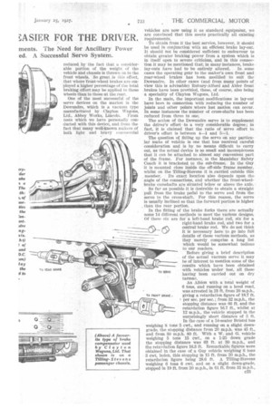
The question oC fitting up the servo on any particular make of vehicle is one that has received careful consideration and is by no means difficult to carry out, as the actual device is so small and inconspicuous that it can be attached to almost any convenient part of the frame. For instance, in the Maudslay Safety Coach it is bracketed to the sub-frame. In the Guy it is mounted close inside the off-side frame member, whilst on the Tilling-Stevens it is carried outside this member. Its exact location also depends upon the angle of the connections, and whether the front-wheelbrake camshafts are situated below or above the axle.
So far as possible it is desirable to obtain a straight pull from the brake pedal to the servo and from the servo to the cross-shaft. For this reason, the servo is usually inclined so that the forward portion is higher than the rear portion.
In the fitting of the brake forks there are actually some 14 different methods to meet the various designs. Of these six are for a left-hand brake rod, six for a right-hand brake rod, and two for a central brake rod. We do not think It is necessary here to go into full details of these various methods, as they merely comprise a long list which would be somewhat tedious to our readers.
Before giving a brief description
of the actual vacuum servo it may be of interest to mention some of the results which have been obtained with vehicles under test, all these having been carried Out On dry tarmac.
An Albion with a total weight of 6 tons, and running on a level road, was arrested in 23 ft. from 20 m.p.h., giving a retardation figure of 18.7 ft. I per sec. per sec.; from 32 m.p.h., the stopping distance was 66 ft. and the retardation figure 16.7 ft., whilst at 12 m.p.h., the vehicle stopped in the surprisingly short distance of 5 ft. In the ease of a 54-seater Bristol bus weighing 8 tons 5 cwt.; and running on a slight downgrade, the stopping distance from 20 m.p.h. was 45 ft., and from 30 m.p.h. 80 ft. With a W. and G. vehicle weighing 5 tons 15 cwt., on a 1-25 down grade the stopping distance was 63 ft. at 30 m.p.h., and the retardation figure 16.3 ft. Remarkable figures were obtained in the case of a Guy vehicle weighing 6 tons 3 cwt. laden, this stopping in 15 ft. from 20 m.p.h.., the retardation figure being 28.6 ft. A Tilling-Stevens weighing 6 tons 6 cwt. and On a slight down-grade, stopped in 19 ft. from 20 m.p.h., in 61 ft. from 31 m.p.h., and in 50 ft. from 34.0 m.p.h., the last test giving a retardation figure of 23 ft.
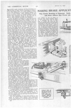
The principle employed in the Dewandre servo is extremely clever and, actually, simple in operation, although somewhat difficult to explain. What may be called the servo motor consists of a cast-aluminium cylinder containing a piston connected by a short length of roller chain to the end of a fairly long lever which is fulcrunied at its centre to the lower end of a second and shorter lever, or, perhaps, it would be better to call it a link, itself pivoted on a pin passing through an aluminium casing which, in the new commercial model, is bolted to the cylinder proper. At its uppen end the first lever is bored out slightly larger than the pivot pin for the link, the actual clearance being approximately 2.5 mm., whilst this portion of the lever is also connected to a small rocking lever which operates the vacuum and atmospheric valves, which are also mounted above the main cylinder, but at the far end.
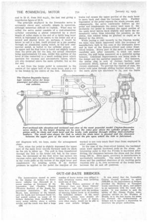
A rod from the brake pedal is connected to the centre of the upper half of the main lever, and a rod to the brakes to the centre of the link. Reference to our diagrams will, we hope, make the arrangement clear.
Now, when the pedal is slightly depressed the upper part of the main lever travels forward until its slack on the pin i$1 taken up. The pull is then transferred through the link to the brake rod, but, in the meantime, the movement of the first lever has opened the vacuum valve, and Ihe piston after taking up the slack in the chain pulls on the bottom of the min lever and supplements the • braking action. If no further pressure be applied to the pedal the reaction of the brake rod causes the upper portion of the main lever to move back and close the vacuum valve. Further depression of the pedal repeats the whole process, and, consequently, the servo continually follows up the pedal and supplements the power used upon it. Immediately the pedal is released the upper portion of the main lever moves back slightly and opens the atmospheric valve, thus releasing the pressure on the piston, this release being as gradual or rapid as is desired by the driver. While paying a visit recently to the Clayton works, we were very much impressed with the accuracy of manufacture, both in the ease of the Dewandre Servo and in that of the Rubury-Alford and Alder frontwheel brakes. Every part of the servo is tested most carefully and, after assembly, is tried out under suction, the pull being measured on a powerful spring balance. Continual improvements are being made in the design and the material employed. For instance, the piston ring is now of chrome leather, most accurately fitted, instead of the wick material previously employed. To prevent the ingress of dust, the brake rods pass through sliding leather shutters. All the main parts are machined to jig, and the limits
worked to are very much finer than those employed in other countries.
In the case of the front-wheel brakes, the hardened cams work against hardened pads on the shoes. An interesting point is that the Ferodo is machined after fittting, the clearance between the shoes and the drunk being .000 in. Here again, accuracy in manufacture is particularly noticeable. The small movement in the shoes and the combined clearance of six working parts
requires only in. free movement of the brake lever between the on and off positions.