


• A NEW SUSPENSION SYSTEM.
Page 32
If you've noticed an error in this article please click here to report it so we can fix it.
A Resume of Recently Published Patents.
' In the ingenious suspension system for a cat, which is described hy P. H. Johnson in 'specification No. 154994, the ehasWLS is carried from its axles by means of rapes. There are, as might well be imagined, many different methods of carrying this suspension into effect, and the descriptions and illustratioes of altenratiye designs occupy a considerable pro'portion of the subjectmatter a this patent specification. It will suffice for our purpose, no doubt, to describe one of
them. In this, the first ene to which
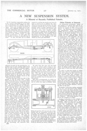
reference is made in the specification, an endless rope is used, passing right round the car and serving as a common suspension system for both axles. It Will be observed, on reference to our illustrations, that the rope passes over a series a pulleys, some of which are mounted on brackets fixed to the axles, the others being attached, by similar means to the framework of the chassis.
Tracing this rope along one side of the chassis, it will bo notedthat., coming from across the front end, it passes first round a grooved pulley, which is carried by what corresponds to a front dumbiron. It passes thence over another pulley, which is supported by an extension of the steering pivot., and from there again under another one quite close to the. steering pivot, but carried by a bracket fixed on the side member of the frame. Thence it runs along the side of the chassis to a point which approximately coincides with the usual position of the front bracketof the rear road spring. Here a pivot is fixed, carrying a pair of pulleys, one at each endt of a double-armed lever. Attached to the lever is a segment of a sprocket wheel, to which a short length of chain is-attached. The free end of the chain is coupled to a eulastantial tension spring, which, again, at. its rear end, is adjustably secured to a bracket riveted to the frame. The rope coming from the front end of the chassis passes under the lower one of these two pulleys, round the rear edge of it, underneath the upper pulley, round the front edge of that, emerging on the top edge in a rearward direction. The rope, it will be gathered, follows an S-shaped path, 'and the arrangement of the spring and chain to which we have referred is such that it continuously imposes a tension upon the TOT*, and, in the event of any stretching, will maintain that
is24 •
tension by pulling the double-arm lever in 8uch a manner as to tighten the rope.• After leaving this double pulley, the rope continues towards the rear of the chassis, passing under a pulley mounted on the bracket of the frame and_ located near the rear axle, over another pulley mounted on a bracket on the rear axle, then round another which is disposed seas to direct the rope, as it leaves, across the frame to the other side, where the arrangement is the duplicate of that which we have just described. .
In order that the rope xvi I not tend to wear in certain parts owing to continuous movement round par icular pulleys, one of the latter is fitted with a ratchet and pawl gear, which ensures that the pulley only revolves in one direction. The rope is thus constrained to creep gradually round the chassis, continuously exposing hitherto unused portions to possible wear in the grooves of the pulleys.
The other arrangements, to which. we have not space to refer at length, include one in which the rope is divided, there
being one portion of it at each side of the chassis and no connection between the two sets, and another in which the rope is divided, one part being dispoted"so as to control the movements of the front axle, the other being similarly arranged to take care of those of the rear axle.
This suspension is chiefly of interest asbeing unusual, and we are doubtful if it would be effective on heavy vehicles.
Other Patents of Interest.
An interesting carburetter design is the subject of a patent this week by G. Con.stantinesco an inventor who is well known to reaCiera of The Con,mercial Motor.' As illustrated and described in the specification, which is numbered 155001, the jet is centrally disposed with regard to the float chamber. It is inverted, however, andprojects downwardly into the induction pipe, which is placed below that chamber. Its area is controlled by a needle valve from above, and the fuel enters the jet by means of a passage, .the open end of which is slightly above the usual level of the fuel. This opening, again, is surrounded by a partition which is continued up through the top of the float chamber proper, emerging into -a narrowspace formed in the lid of that chamber. This space is in communication with the induction pipe, on the engine side of the butterfly throttle valve. When the. engine is at rest, -petrol does not enter the jet, because of the fact that the entrance to that jet is above the level of the fuel in the float chamber. When the engine is turned over by hand, however, with the throttle valve, as is cuStomary, practically shut, a considerable suction is caused in the induction .pipe,on the engine side of the throttle, and this is transferred to the inside of the partition which surrounds thek jet opening and has the effect of lifting petrol inside that partition until it flows over the wall of the jet!'
In order to limit the height to which petrol rises, there is communication between the passage . in the cover of the float chamber and that chamber, by means of a small automatic valve, the weight, of. which keeps it closed until the vacuum readies a certain figure. When the suction lies reached that critical point, the valve lifts, and' vacuumis also formed.in the float chamber itself. This, in combination with a small hole bored in the wall of the float chamber, controls the flow of the fuel:
In another carburetter design, patented by A. Cox, and described in No. 155100, the fuel enters the float chamber from the top, and the float itself is surrounded by an inner chamber of sheet metal with gauze-covered apertures, through which the petrol must pass 'on its way out of 'the chamber. This float chamber thus serves the purpose of a filter
Another carburetter is. this subject of No. 133289.; the patentee being M. G. Chandler. This is of the type in which a vacuum feed apparatus 33_ embodied within the carburetter itself. The patentee, recognizing that, for certain conditions of engine running,-the vacuum in the carburetter is not sufficient to lift the petrol in all circumstances, as, for example, when ascending a steep hill on a ear in which the, tank is at the back of the chassis, intensifies that vacuum by a suitable arrangement of tenturi passages or tubes within the choice tube itself.
No. 155064, by R. Clocifrey, describes a simple type of petrol filter. The object of the invention is to design a device of this kind in such a manner that it can be produced cheaply and readily.