


OVERHAULING THE ALBION.
Page 24
Page 25
Page 26
Page 27
If you've noticed an error in this article please click here to report it so we can fix it.
No. 7. —The 32 h.p. 3 ton Chassis. A Chain-driven Model of Remarkably Clean Design and Pronounced Accessibility.
THIS ARTICLE is of particular interest, as•it is the first one of this series dealing with a chain-driven commercial vehicle, and of this type of vehicle the Albion is one of the best known and most successful.
Chain drive has its exponents and detractors, but when it comes to making a complete overhaul we are certainly of the opinion that the chain-thiven vehicle is extremely hard to beat ; compared with the chaindriven Albion, the average live axle model appears complicated, although to some thinkers the reverse might appear to be the case. It will be noted that we write of the chain-driven Albion only ; this is because we are dealing with the matter of overhaul, and the Albion live axle model has not been on the market, or in the hands of users, for a period sufficiently long to necessitate complete overhauls, and, therefore, the makers can. hardly be called epon to give their experience and hints with regard to the overhaul of this particular type. In dealing with the 3 ton Albion, we shall practically cover the range of chain-driven. models, as they are all manufactured on lines so nearly similar in design, and, in fact, commencing on January 1st this
year, all the Albion engines used on the chain-driven models were made interchangeable, a feature of considerable interest to users of mixed fleets.
. Dismantling Before Overhaul.
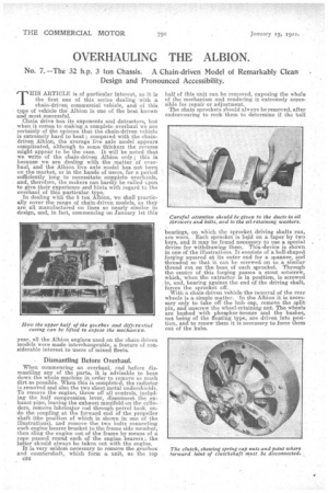
When commencing an overhaul, end before dismantling any of the parts, it is advisable to hose down the whole machine in order to remove as much dirt as possible. When this is completed, the radiator is removed and also the two sheet metal undershields. To remove the engine, throw off all controls, including the half compression lever, disconnect the exhaust pipe, leaving the exhaust manifold on the cylinders, remove lubriea.tor rod through petrol tank, undo the coupling at the forward end of the propeller shaft (the position of which is shown in one of the illustrations), and remove the two bolts connecting each engine bearer bracket to the frame side member, then sling the engine out of the frame by means of a rope passed round each of the engine bearers ; the latter should always be taken out with the engine.
It is very seldom necessary to remove the gearbox and countershaft, which form a unit, as the top c24 half of this unit can be removed, exposing the whole of the mechanism and rendering it extremely aecessible for repair or adjustment. The chain sprockets should always be removed, after endeavouring to rock 'them to determine if the ball
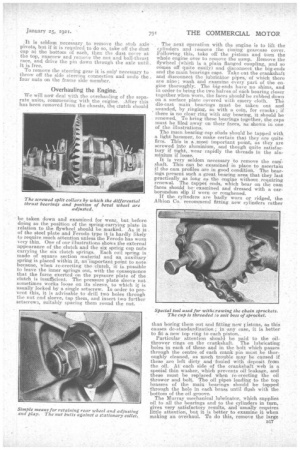
bearings, on which the sprocket driving shafts run, are worn. Each sprocket is held on a taper by two keys, and it may be .found necessary to use a special device for withdrawing them. This-device is shown in one of the illustrations. It consists of a bell-shaped forging squared at its outer end for a 2panner, and threaded so that it can be screwed on to a similar thread cut an the boss of each sprocket. Through the centre of this forging passes a stout setscrew, which, when the extractor is in position, is screwed in, and, bearing against the end ef the driving shaft, forces the sprocket off.
With a chain-driven vehicle the removal of the rear wheels is a simple matter. In the Albion it is necessary only to take off the hub cap, remove the split pin, and unscrew the wheel-retaining nut. The wheels are bushed with phosphor-bronze and the bushes, not being of the floating type, are driven into position, and to renew them it is necessary to force them out of the hubs. It is seldom necessary to temove the stub axle pivots, but if it is required to do so, take off the dust cap at the bottom of each, then the dust cover at the top, unscrew and remove the nut and ball-thrust race, and, drive, the pin down through the axle until, it is free.
To remove the steering gear it is only necessary to throw off the side steering connection and undo the four nuts on the frame sidemember.
Overhauling the Engine.
We will no* deal With the overhauling of the separate units, commencing with the engine. After this has been removed from the chassis, the clutch should
be taken down and examined for wear, but before doing so the position of the spring-carrying plate in relation to the flywheel should be marked. As it is of the steel plate and Fe rode type it is hardly likely to require, much attention unless the Ferodo has worn very thin. One of our illustrations shows the external appearance of the clutch and the six spring cap nuts carrying the six clutch springs. Each coil spring is made of square section Material and an auxiliary spring is placed within it, an important point to note because, when re-erecting the -clutch, it is possible to leave the inner springs out, with the consequence that the foree exerted on the pressure plate of the clutch is insufficient. The pressure plate sleeve nut sometimes works loose on its sleeve, to which it is usually locked by a single setscrew. In order to prevent this, it is advisable todrill two holes through -the nut and sleeve., tap them, and insert two further setscrews, suitably spacing them round the nut.
The next Operation with the engine is to lift the cylinders and remove the timing gearease cover.
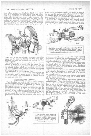
ollowing this, take off the pistons and turn the whole engine over to remove the sump. Remove the flywheel (Which is a plain flanged coupling, and 80 cemes off quite easily) and disconnect the big-ends and the main bearings caps. Take out the crankshaft and disconnect the lubricator pipes, of which there are nine; wash and examine every part of the engine thoroughly. The big-ends have no shims, and in order to bring the two halves of each bearing closer together, when worn, the faces should be rubbed down on a surface plate covered with emery cloth. The die-cast main bearings. must be taken out and sounded, by ringing, as With a coin, for cracks; if there is no clear ring With any bearing, it should be renewed. To bring these bearings together, the caps must be 'filed away on their faces, as shown in one of the illustrations.
The main bearing cap stitch should be tapped with a, light hammer, .to make certain that they are quite firm. This is a .most iinportant point, as they are screwed into aluminium, and though quite satisfactory if tight, wear rapidly the threads in the aluminium if loose.
It is very seldom necessary 'to remove the cardshaft. This can be examined in place to ascertain if the cam profiles are in good condition. The bearings present such a great bearing area that they last practically as long as the engine without.requiring renewal. The tappet ends, which bear on the cam faces should be' examined and dressed with a carborundum slip if worn or roughened. If the cylinders are badly worn or ridged, the Albion Co. recommend fitting new cylinders rather than boring them out and fitting new i stons, as this causes dc-standardization; in any case, it is better to fit a, new top ring to each piston.
Particular attention should be paid 'to the oilthrower rings on the crankshaft. The lubricating holes in each of these and in the bolt which .pass.es through the centre, of each crank pin must be thoroughly cleaned, as much trouble may be caused if these are left dirty and fouled with deposit from the oil. At each side of the crankshaft web is a special thin washer, which prevents oil leakage, and these must be replaced when re-erecting the oil thrower and belt. The oil pipes leading to the top brasses of the main bearings should be tapped through the hole in each brass until flush with the 'bottom of the Di] groove.
The Murray mechanical lubricator, which supplies oil to all the bearings and to the cylinders in turn, gives very satisfactory results, and 'usually requires little attention, but it is better to examine it when making an overhaul. To do this, remove the large
skew wheel at the top, this being fitted on a taper and on a somewhat delicate shaft must be dealt with very carefully and levered up from opposite sides; then lift eff the cover, thus exposing the mechanism, and make certain that the two ratchet .springs are correctly -positioned, i.e., that they are bedding well into the ratchet teetha finger should be rubbed along the latter, and if they are rounded they should be filed sharp and -to the proper angle.
To do this, it will be necessary to remove the disc, which can be done by taking out two _split pins, releasing the two coil springs, and pulling the disc off the spindle. At the lower part of each cylinder isa circular groove, to which oil is forced from the pump. In replacing the cylinders, care must be taken to see that the special washers which are required between the oil pipes and the ducts leading to these oil grooves are correctly positioned in the recesses fermed for their reception in the crankcase face. The water pump is driyen by an extension of the fan spindle, and, its gland must be repacked with hemp and tallow, care being taken to tighten equally the nuts at each end.
Overhauling the Gearbox..
Plain bearings are used to a great extent throughout the change-speed mechanism, although the final drive bevel wheel runs on annular ball races, and ball thrust races are used where required. As with the engine bearings, no shims are employed, and the bearings are let up in the same way, as with the former. When replacing each hearing cap nut locking plate, if the plate will not quite fit over the nut do not slack the nut back ; if not much out, it is permissible to take the nut round a trifle more, but if this would strain the threads, it is better to remove the nut and file its face until, when screwed up tight, tho locking plate fits over it exactly ; in this ease also, as the studs are carried in the aluminium casing, it is essential to see that they are tight. Between the constant mesh and second speed pinions on the secondary shaft is a double ball thrust bearing held in a socket provided with a steel cap. A portion of the shaft passing through this bearing is screwed at either side and provided with screwed split collars by which the Whole shaft can be adjusted endways in either direction. Normally, the split collars are locked in position by short bolts. Means for adjusting the end play and position of the bevel wheel are afforded by two screwed split collars at each end of the differential cage. The inner two collars position the bevel wheel, whilst the other two limit the end play.
The change-speed gears are of the constant mesh type' brought into action by means of dog clutches. The teeth on the latter may wear, and, if so, should be ground .square.
If the chain sprockets are only slightly worn, grind off the hooks caused by wear ; but if badly worn, they should be renewed.
To adjust the gear striking-mechanism, take off the gearbox cover. When the gear lever is in the correct position, the dogs should be well into mesh, and if this is ndt so a means of adjustment is afforded by the fork ends at the forward ends ofthe two long gear-operating rods. To effect the adjustment on either rod, the fork pin must be withdrawn, the lock-, ing nut slacked back, and the fork turned one way or the other as is required. If this adjustment is insufficient, owing to any backlash which may have developed, the radius of action of the lever
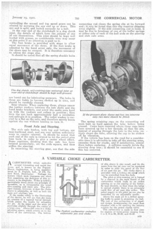
controlling the second and top speed gears can bealtered by screwing the eye end up or down. This eye end is split, and locked normally by a bolt. At the rear end of the clutchshaft is a dog clutch joint, the details of which form the _subject of one of our illustrations. This joint should be kept well loaded with grease, as considerable wear may occur at this point if no attention is paid to it. The foot brake is provided with stops to allow equal movement of the shoes. If the foot brake is adjusted by the hand screw only, the movement of the shoes may be unequal. It is therefore necessary to adjust the stops also. It should be noted that all the spring shackle bolts are bored out for lubricating purposes. The holes in these are liable to become choked up in time, and should be carefully cleaned.
Rear wheels: When replacing these, always renew the leather washers between the hub shells and the hand brake brackets, and screw the castle nuts hard up with the washers and collars in position ; then turn the nut back approximately half a revolution and split-pin it in position. The collet washer is carried by a flat on the axle, and therefore merely bears against the nut without tending to turn it.
Front Axle and Steering.
The stub axle bushes, both toP and bottom, are 'case-hardened steel, and are very seldom sufficiently worn to require renewal. It should be noted that each end of the axle is twisted to let the swivel pins lean back, in order to give a caster wheel .effect. Some repairers, thinking that the axle has been twisted accidentally, set the ends square, and thus stiffen the steering.
In examining the steering gear, see that the side
connecting rod, clears the spring clip at its forward end; it may be found that this clip requires chipping away slightly. If the side connecting rod is loose, it may be due to breakage of one of the buffer springs at either side of each of the ball ends on the steering and stub, axle arms.
The spring retaining caps on the connecting rod must butt up hard against the tube before being pinned. Cases have occurred where these caps have been screwed. up for a few threads, so that the pin, instead of passing through the hole in the tube, entirely clears the tube, allowing the cap to be shaken off by vibration.
If the vehicle has been on the road for a considerable time it is-advisable to take off the steering arms,
• examine them for cracks, and if satisfactory, anneal them before replacing. A collision usually twists the steering drop arm ; it should be examined to see if this has occurred.