


A German Two-stroke Engine
Page 56
If you've noticed an error in this article please click here to report it so we can fix it.
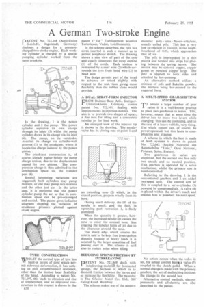
PATENT No. 722,168 (Auto-Union I G.m.b.H., Ingolstadt, Germany) discloses a design for a pressurecharged two-stroke engine. Each working cylinder is charged by a special pumping cylinder worked from the same crankpin.
In the drawing, 1 is the power cylinder and 2 the pump. The power cylinder aspirates its own charge through its inlets (3) whilst the pump cylinder draws in its charge via its inlet (4). The pump, on its outstroke, iransfers its charge via cylinder-wall grooves (5) to the crankcase, where it boosts the charge induced by the power piston.
The crankcase compression is, of course, already higher before the pump charge arrives, due to the displacement caused by two pistons. The compression charge is then admitted to the combustion space via the transfer port (6).
Several interesting variations are suggested; both cylinders may pump mixture, or one may pump rich mixture and the other just air. In the latter case, it is preferred that the power cylinder pump the air, so that its cod'. bustion space can be pre-scavenged and cooled. The patent gives indicator diagrams showing the variation of crankcase pressure plotted against crank angles.
TYRE CONSTRUCTION WHILST the normal type of tyre has Vlf built-in layers of cord which permit sideways deformation, it has nothing to give circumferential resilience, other than the limited local flexibility of the tread. According to patent No. 721,697, this leads to abrasion and rise of temperature, and an improved construction in this respect is shown in the n30 patent (" Est " Etablissement Sciences Techniques, Vaduz, Leichtenstein).
In the scheme described, the tyre has cords inserted in such a manner as to permit peripheral stretch. The drawing shows a side view of part of the tyre and clearly illustrates the wavy outline (I) of the cords. Each section is restrained by a steel wire (2) which surrounds the tyre from bead wire (3) to bead wire.
The design permits part of the tread to advance or retard slightly with respect to the rest, thus giving more flexibility than the rubber alone would provide.
A DUAL SPRAY-FORM INJECTOR
FROM Daimler-Benz A.G., StuttgartUhtertiirkheim, Germany, comes patent No. 722,161, dealing with improvements in injection nozzles. The aim is to provide two shapes of spray, a fine mist for idling and a concentric tubular jet for load work.
An enlarged view of the injector tip is shown in the drawing. The needlevalve has its closing seat at point 1 and an extending nose (2) which, in the closed position, projects wholly from its bore.
During small delivery, the lift of the needle is small, and the fuel,' in squeezing past restriction 3, is finely atomized.
When the quantity is greater, however, the increased needle-lift causes the nose to enter the conical bore, thus creating the tubular form of jet due to the clearance around the nose.
The sharp edge which creates the mist is said to be kept free from carbon deposits because at heavy loads it is scoured by the larger quantities of fuel passing over it. The scheme is said also to reduce noise when idling.
REDUCING SPRING FRICTION SY INTERLEAVING
PATENT No. 721,949 deals with interleaving material for laminated springs, the purpose of which is to diminish friction between the leaves and so increase the flexibility. The patentee is The Glacier Metal Co., Ltd., 368 Ealing Road, Wembley.
The scheme makes use of the modern material poly tctra fluor° ethylene, usually called ptfe. This has a very low co-efficient of friction, in the neighbourhood of 0.05, which approaches that of ice.
The ptfe is impregnated in a thin matrix and formed into strips for placing between the spring leaves. The matrix may be sintered copper, copper gauze or punched copper strip. The ptfe is applied to both sides and attached by hot-pressing.
An alternative method utilizes a mixture of ptfe and Bakelite powder, the mixture being hot-pressed to the required form.
A MULTI-SPEED GEAR-SHIFTING SYSTEM
TO obtain a large number of gear ratios it is a well-known practice to place two gearboxes in series. This, however, means that at some time the driver has to move two levers while changing; this can be confusing, and in the case of a heavy vehicle, very tiring. The whole system can, of course, be power-operated, but this leads to complication and expense.
A scheme in which the best is made of both systems is shown in patent No. 722,042 (Societe Nouvelle des Automobiles " Unic," Quai National, Puteaux, Seine, France).
Two gearboxes in series are employed, but the second one has only two speeds and no neutral position. This gearbox is operated by a servo mechanism, whilst the primary one is hand-controlled.
Referring to the drawing, 1 is the conventional gearbox and 2 an added two-speed unit. The control arm of this is coupled to a servo-cylinder (3) powered by compressed air. A valve (4) is placed within the driver's reach and enables him to preselect his next speed.
No action occurs when the valve is set, the actual control being a valve (5) coupled to the clutch pedal. When a normal change is made with the primary gearbox, the act of declutching initiates the change in the second box.
Alternative control methods, electropneumatic and all-electric, are also described in the patent.