


allies Itself in a 6-tonner
Page 35
Page 34
Page 36
Page 37
If you've noticed an error in this article please click here to report it so we can fix it.
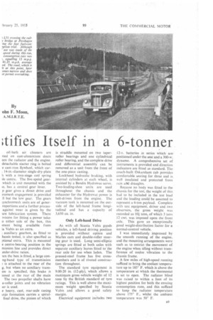
By ohn F. Moon,
A.M.I.R.T.E. IN accordance with the well-proved Scania Vabis policy of good design and solid construction, the L51 series of 6-ton chassis has a potentially long life of economic and trouble-free service. A large margin of power is given by the four-cylindered oil engine, and exceptional braking, a high rate of acceleration and a low fuel-consumption rate at high speeds are commendable points.
It may be thought unusual to use a large four-cylindered engine in a 6ton chassis, but the reason for this lies in the standardization of component parts for all Scania Vabis four-, sixand eight-cylindered engines. The high-power output of this engine is not wasted in the chassis and the high rear-axle ratio of 5.11 to 1 enables a lively performance to be obtained from this power.
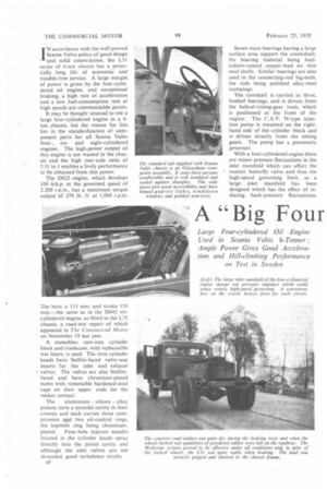
The D422 engine, which develop; 100 b.b.p. at the governed speed of 2,200 r.p.m., has a maximum torque output of 278 _lb. ft. at 1,000 r.p,m.
The bore is 115 mm. and stroke 150 mm.—the same as in the D642 sixcylindered engine, as fitted to the L71 chassis, a .road-test report of which appeared in The Commercial Motor on November 19 last year.
A monobloc cast-iron cylinder block and crankcase, with replaceable wet liners, is used. The twin cylinder heads have Stellite-faced valve-seat inserts for the inlet and exhaust • valves. The valves are also Stellitefaced and have chromium-plated stems with removable hardened-steel caps on their upper ends for the rocker contact.
The aluminium silicon alloy pistons have a toroidal cavity in their crowns and each carries three compression and two oil-control rings, the topmost ring being chromium plated. Four-hole injector nozzles located in the cylinder heads spray directly into the piston cavity and although the inlet valves are not shrouded, good turbulence results.
B8
Seven main bearings having a large surface area support the crankshaft, the bearing material being leadindium-coated copper-lead on thin steel shells. Similar bearings are also used in the connecting-rod big-ends, the rods being polished alloy-steel stampings.
The camshaft is carried in three, bushed bearings, and is driven from the helical-timing-gear train, which is positioned at the front of the engine. The C.A.V. N-type injection pump is mounted on the righthand side of the cylinder block and is driven directly from the timing gears. The pump has a pneumatic governor.
With a four-cylindered engine there are minor pressure fluctuations in the inlet manifold which can affect the venturi butterfly valve and thus the high-speed governing limit, so a large inlet manifold has been designed which has the effect of reducing back-pressure fluctuations.
oil-bath air cleaners are tied on cast-aluminium ducts een the radiator and the engine. detachable starter ring is bolted e cast-iron flywheel, which car. 14-in.-diameter single-dry-plate h with a two-stage coil spring de centre. The five-speed gearwhich is unit mounted with the le, has a central gear lever.
p gear gives a direct drive and iromesh engagement is provided 11 but the low gear. The gears iynchromesh units are of generroportions and a further precauagainst wear is given by the ure lubrication system. There pvision for fitting a power take o either side of the box, this iment being available from ia Vabis as in extra. , L auxiliary gearbox, as fitted to hassis tested, is also specified as ptional extra. This is mounted e centre-bearing position in the mission line and provides direct older-drive ratios.
ten the box is fitted, a large conng-band type of transmission is attached to the rear of the g, but when no auxiliary transonis specified, this brake is ioned at the rear of the main The two propeller shafts have e-roller joints and no vibration )er is used.
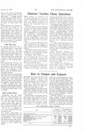
e heavy, cast, rear-axle casing injo formation carries a spiralfinal drive, the pinion of which is straddle mounted on two taperroller bearings and one cylindrical roller bearing, and the complete drive and differential assembly can be removed as a unit from the front of the one-piece casting.
Lockheed hydraulic braking, with internal cylinders at each wheel, is assisted by a Bendix Hydrovac servo. Two-leading-shoe units are used throughout the chassis and the exhauster for the Hydrovac power is belt-driven from the engine. The vacuum tank is mounted on the outside of the left-hand frame longitudinal and has a capacity of 3,650 Cu. in.
Only Left-hand Drive
As with all Scania Vabis goods vehicles, a left-hand driving position is provided . without option and Marles cam and double-roller steering gear is used. Long semi-elliptic springs are fitted at both axles with separate auxiliary leaves fitted to the rear axle for use when laden. The pressed-steel frame has five crossmembers and is of riveted construction throughout.
The standard tyre equipment is 9.00-20 in. (12-ply), which allows a maximum gross .vehicle weight of 12 tons by the British standard of tyre ratings. This is well above the maximum weight specified by Scania Vabis and allows a good safety margin.
Electrical equipment includes two
12-v. batteries in series which are positioned under the seat and a 300-w. dynamo. A comprehensive set of instruments is provided and direction indicators are fitted as standard. The coach-built Oskarsham cab provides comfortable seating for three and is. well insulated and protected from rain did draughts.
Because no body was fitted to the chassis for the test, the weight of this had to be included in the test load and the loading could be assumed to represent a 6-ton payload. Complete with test equipment, driver and two observers, the gross weight was recorded as 10-i tons, of which 3 tons 12 cwt. was imposed upon the front axle. This gave an exceptionally good weight-distribution factor for a normal-control vehicle.
I was immediately impressed by the smooth running of the engine, and the mounting arrangements were such as to restrict the movement of the engine when idling without transference of undue vibration to the chassis frame.
A -few miles of high-speed running sufficed to bring the coolant temperature up to 185° F. which is above the temperature at which the thermostat is set to open. The radiator blind was raised to within a foot of its highest position for both the ensuing consumption runs, and this sufficed to keep the radiator temperature above 175° F., whilst the ambient temperature was 50° F.
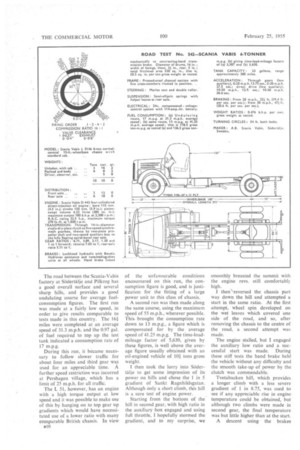
The road between the Scania-Vabis factory at Sodertalje and Pilkrog has a good overall surface and several sharp hills, and provides a good undulating course for average fuelconsumption figures. The first run was made at a fairly low speed, in order to give results comparable to tests made in this country. The 161 miles were completed at an average speed of 31.3 m.p.h. and the 0.97 gal. of fuel required to top up the test tank indicated a consumption rate of 17 m.p.g.
During this run, it became necessary to follow slower traffic for about four miles and third gear was used for an appreciable time. A further speed restriction was incurred at Pershagen village, which has a limit of 25 m.p.h. for all traffic.
The L 51, however, has an engine with a high torque output at low speed and it was possible to make use of this by hanging on to top gear up gradients which would have necessitated use of a lower ratio with many comparable British chassis. In view
nlO
of the unfavourable conditions encountered on this run, the consumption figure is good, and is justification for the fitting of a large power unit to this class of chassis.
A second run was then made along the same course, using the maximum speed of 55 m.p.h., wherever possible. This. brought the consumption rate down to 13 m.p.g., a figure which is compensated for by the average speed of 41.25 m.p.g. The time-loadmileage factor of 5,630, given by these figures, is well above the average figure usually obtained with an oil-engined vehicle of 101 tons gross weight.
then took the lorry into Sodertalje to get some impression of its power on hills and chose the 1 in 5 gradient of Sankt RagnhiIdsgatan. Although only a short climb, this hill is a sure test of engine power.
Starting from the bottom of the hill in second gear, with high ratio in the auxiliary box engaged and using full throttle, I hopefully stormed the gradient, and to my surprise, we smoothly breasted the summit with the engine revs. still comfortably high.
I then "reversed the chassis part way down the hill and attempted a start in the same ratio. At the first attempt, wheel spin developed on the wet leaves which covered one side of the road, and so, after removing the chassis to the centre of the road, a second attempt was made.
The engine stalled, but I engaged the auxiliary low ratio and a successful start was made. During these stiff tests the hand brake held the vehicle without any difficulty and the smooth take-up of power by the clutch was commendable.
Tvetabacken hill, which provides a longer climb with a less severe gradient of 1 in 8.75, was used to see if any appreciable rise in engine temperature could be obtained, but although two climbs were made in second gear, the final temperature was but little higher than at the start.
A descent using the brakes mcd up the drums considerably had no adverse effect on the cing power. A longer descent id have been preferable because large frictional area of the rigs would require severe testing ire signs of brake fade were iced.
he speedometer was checked for iracy and was found to be ect up to about 35 m.p.h., so short-distance trials were then lucted along a flat stretch of :!rete-surfaced road adjacent to Scania Vabis factory. The road quite dry and when braking from m.p.h. all four wheels locked, ing vast quantities of powdered )er on the road surface.
Little Time Lag he braking distance of 471. ft. .1 this speed gives a retardation valent to 0.65 g. The perlance from 20 m.p.h. was little impressive, but at this speed only front wheels locked. There was little time lag in the system and il pressure required was directly iortional to the braking effort luced.
ten braking from 30 m.p.h., the t end of the chassis slid across road slightly with all the wheels ed, but at no time was control pletely lost although in wet :her it would be advisable not to full pedal pressure.
::celeration tests were made along same road and it was found that :r times were obtained for both standing-start and rolling-start when low ratio in the auxiliary was engaged. The good synchroaction enabled very fast iges to be made through the gears doubtless contributed in no small to the good times which I was to obtain.
Start in Direct Drive
rolling-start test, for which A-drive in both gearboxes was ged, very nearly caused the le to stall but it was not necesto slip the clutch and the ;mission settled down again by ime 13 m.p.h. was reached. The taken to reach 20 m.p.h. in this was 19 sec., as opposed to sec., when using the low ratio ie auxiliary box.
had several opportunities of ng the L51 during the day, and at high speed it was in no way -ing experience. The controls well placed and the fully adjustseat can be quickly adapted to drivers of any stature and idence.