


A Heating Unit for Single-Deckers
Page 28
If you've noticed an error in this article please click here to report it so we can fix it.
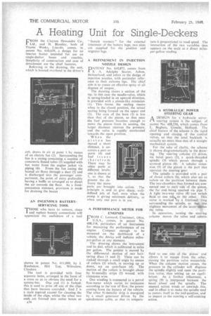
FROM the Clayton Dewandre Co., Ltd., and H. BlomIey, both of Titanic Works, Lincoln, comes, in , patent No. 610,659, a design for an interior heater intended for use on single-decker buses and coaches. Simplicity of construction and ease of
detachment are the chief features. • Referring to the drawing, the unit, which is housed overhead in the driver's cab, draws in air at point 1 by means of an electric fan (2). Surrounding the fan is a casing containing a number of concentric finned tubes (3) supplied with hot water from the engine jacket via piping (4). From the fan casing the heated air flows through a duct (5) and is discharged into the passenger compartment, the point of entry preferably having a baffle so arranged as to direct the air towards the floor. As a frostprecaution measure, provision is made for draining the heater shown in patent No. 611,000, by J. Rtinbaken, Hill Top, Wilmslow, Cheshire.
The tool is provided with four separate items, arranged in the form of a cross so as to obviate the need for a tommy-bar. One end (1) is forked; this is used to prise off any of the clips that have become corroded. End 2 is a male tapered reamer for cleaning the inside of the clips, whilst the other two ends are formed into cutter boxes or
A34
" fen-tale reamers" for the external treatment of the battery lugs; two sizes arc supplied for the positive and negative lugs.
A REFINEMENT IN INJECTION NOZZLE DESIGN
PATENT No. 610,873, comes from S. A. Adolphe Saurer, Arbon. Switzerland, and refers to the design of injection nozzles, with particular reference to their extreme tips. The chief aim is to create an effective spray at all degrees of output.,
The drawing shows a section of the tip; in this case the needle-valve, which it spring-loaded in an upward direction, is provided with a piston-like extension (1). This forms the sealing means when in the closed position, the actual seating being formed on the upper end (2). The area of the bore (3) is less than that of the piston, so that once .the fuel pressure becomes enough to move the piston from its seating, the larger diameter receives the pressure, and the valve is rapidly accelerated towards the open position.
When the piston has moved a short distance, it uncovers a port or ports (4) and fuel issues therefrom. There may be other ports at different levels; one is shown at 5, so that the greater the delivery the more• ports are • brought into action. The principle is said to give sharp, welldefined jets of fuel, even when the pump is giving minimum delivery, as when only one port is in use.
A PERFORMANCE METER FOR ENGINES
FR"C. Leonard, Cincinnati, Ohio, U.S.A., comes, in patent No. 608,114, particulars of an instrument for measuring the performance of an engine. Compact enough to be mounted on the dashboard of a vehicle, the device will indicate milesper-gallon at any moment.
The drawing shows the instrument and its dial, which is calibrated in miles per gallon. The pointer is moved by the differential motion of two hairspring discs (1 and 2). These can be rocked through a small angle by means of rollers (3) which, in moving up or down, act on cam-faces (4). The motion of the rollers is brought about by hi-metallic strips (5) wound with resistance wire.
One winding is connected to a petrol flow-meter which varies its resistance according to the rate of flow, the power coming from the battery of the vehicle. The other hi-metallic strip is energized by a small generator driven by the speedometer cable, so that its tempera
ture is proportional to road speed. The interaction of the two variables thus appears on the scale as a direct milesper-gallon reading.
• A HYDRAULIC POWER STEERING GEAR
PAA DESIGN for a hydraulic servosteering system is the subject of patent No. 608,236, which comes from L. Baghuis, Utrecht, Holland. The chief feature of the scheme is the rapid opening and closing , of the control valves, so that the total backlash is actually no more than that of a straight mechanical system.
For the sake of clarity, the scheme is shown diagrammatically in the drawing. The steering column (1) drives. via bevel gears (2), a quick-threaded spindle (3) which passes through a screwed piston. (4). A tubular extension (5) of the piston is the part that operates the steering gear. The spindle is provided with a pair of thrust collars (6), which also •act as valves on the partition between them. The two chambers thus formed are connected one to each side of the piston, the far end• being reached via pipe 7. A light two-way valve (8) can switch fluid to one side.or the other. This valve is worked by a -frictional ring surrounding the spindle, so that the slightest movement of the latter moves the valve.
In operation, turning the steering column moves the valve and admits
fluid to one side of the piston and allows it to escape from the other, closing the partition valve meanwhile. When the column motion ceases, the pressure in the cylinder will displace the spindle slightly and open the partition valve, thus setting up an equilibrium. As a further refinement, a spring (9) ia interposed between the bevel wheel and the spindle. The manual action winds or unwinds this, and its effect is to make the spindle tend to restore itself to the mid-position, and so impart to the steering a self-centring action.