


A Compressed-air Starter Motor D ES1GNED especially for compression-ignitionsion-ignition engines, and
Page 66
If you've noticed an error in this article please click here to report it so we can fix it.
other units of high power, a starter motor operated by compressed air is shown in patent No. 478,313, by R. Coffman, 4,733, Center Avenue, Pittsburgh, Pa., U.S.A. The device comprises a cylinder containing a spring-returned piston (1) mounted on a series of co-axial quick-threaded sleeves, the innermost one of which carries a ratchet (2) for engagement with the crankshaft member (3). The threaded sleeves are designed to impart a rotary motion to the shaft as the piston is forced to the left by air pressure.
An essential feature of the patent is the use of an initial endwise movement of the central shaft, for the purpose of engaging the dogs before the full starting load is applied.
Independent Suspension with Swinging Half-shafts.
DATNT NO. 478,233 shows a design for a suspension system incorporating swinging half-shafts of a type entirely different from the usual Continental system. The patentee is L.Ballamy, 63, Old Town, London, S.W.4. As will be seen from the drawing, each wheel is provided with its own propeller shaft, complete with bevel-gears at both ends. The casing is pivoted about the differential-shaft centre, with a leaf spring for the resilient member. The latter is attached to a frame bracket at one end and shackled to the axle casing at the other.
Composite Valves for High-compression Engines.
THE employment of high compres
sion ratios renders desirable some means for conducting heat away from the valve heads; such a scheme is described in patent No. 477,907 by H. Weslake, Fuller's Way, Surbiton, Surrey. The valve described has a hollow head and stem, with inserts of a high-conductivity metal such as copper. Such schemes have been suggested in the past, but trouble has arisen over the differences in the rates of expansion of the metals employed and the new design is intended to remedy this trouble.
To this end, the valve is assembled from three pieces, the head-stem s343
member, a steel " lid " (9) carrying a long central spindle (1) and a long copper sleeve (2) to which is attached a countersunk head (3). The copper sleeve is split along its length to permit circumferential expansion and is provided with a slight clearance at the bottom of the bore for lengthwise increase.
In assembly, the copper sleeve is brazed to the underside of the " lid " member, after which the latter is welded to the valve head.
A Double-acting Two-stroke Engine.
UDGING from the number of new
patents covering double-acting engines, the possibilities of stich units seem to .be arousing much interest amongst designers. Such a scheme is the subject of patent No. 478,249, By E. Tilston and W. Chown, 22, Oilerbarrow Road, Hale, Cheshire.
The engine described, which is a twostroke, and equally suitable for light fuel or oil, employs a piston fitted with upper and lower extensions sliding in guide bushes flanged into the cylinder. The two working spaces thus formed communicate alternately with a central ring of ports (5) for exhaust purposes. The fresh charge arrives under pressure at a conduit (6) and, in the position shown, flows down the hollow trunk and enters the lower working space via port 4 as the exhaust is leaving. When the piston is in its lowest position, port 2 acts similarly for the upper space. The engine is equipped with water passages around the whole length of the cylinder, whilst the central trunk is cooled by a long loop of tube (not shown) which enters and leaves via plug I. To assist the guidance of the trunk, a cross-head piston (3) is provided, provision being made for the escape of air from the space so formed,
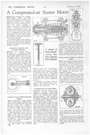
Torque-converter Progress: A German Design.
THE ratio-range of a torque-converter is often insufficient to cover all requirements, and it is usual to fit a reduction gear to provide a low-speed range. To achieve this, without the need for an additional clutch, is the object of a design shown in patent No. 478,088, by Auto-Union A.G., Chemnitz, Germany.
The converter comprises a driving shaft (5) which carries the pump wheel (3). The turbine wheel (2) forms the driven member, and is attached to the output shaft (4), to which a mechanical two-speed box (not shown) is connected. The third member of the gear is the outer casing (6) which is held from rotating by a band brake (1), which brings the torque-converter into action.
The patent is based on the principle of releasing this band brake during the operation of changing gear in the twospeed box, thus relieving the drive momentarily while the gears are beingshifted.