


Tractors in the W.D. Trials.
Page 2
Page 3
Page 4
If you've noticed an error in this article please click here to report it so we can fix it.
The Thornyeroft.
The machine ■vhich we are able I:0 illustrate and describe this week is that which has been built by John I. Thornycroft and Company, Limited, at its Basingstoke works for the trials. This company has, without doubt, the widest experience in the use
of heavy oils for internal-combustion .engines of any of the many motormanufacturing concerns in this coontry, and probably throughout the world, and it is not surprising therefore that the machine which it has produced to compete in the trials, which commence on Monday next, should hold out promise of a very satisfactory performance throughout the various tests to which the competing machines will be submitted. Both the War Department and the Indian Government have already in use sev
eral heavy oil lractcrs which were built at Thurnycroft's works, and we frequently hear excellent reports of their behaviour hi hard service.
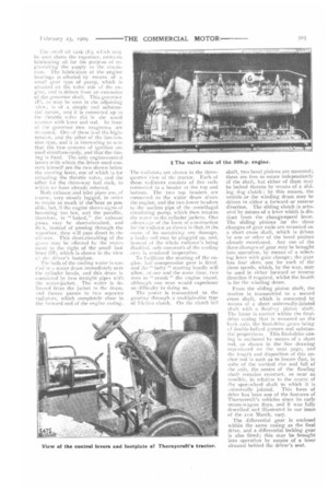
The particular model with which we are now dealing larger than any previously built by this maker, It is driven by a soh.p. engine, having four cylinders each six inches in diameter, with a 7-inch piston stroke, and the above-stated power is developed with the engine running at Sso revolutions per minute. The cylinders are cast in pairs with ample water-jackets, and all the valves are arranged on one side. The crankcase is provided with very large inspection doors, through which, if desired, any one of the pistons, complete with its connecting rod, may be withdrawn for the purpose of repairs or renewals. This can be done without disturbance of any other part of the mechanism.
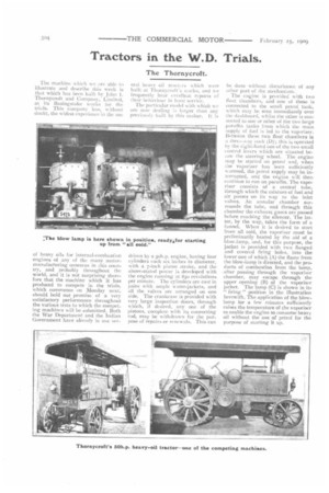
The engine is provided with two float chambers, and one of these is connected to the small petrol tank, which may be seen immediately over the dashboard, whilst the other is connected to one or other of the two large paraffin tanks from which the main supply of fuel is led to the vaporiser. Between these two float chambers is a three-way cock (I)); this is operated by the right-hand one of the two small control levers which are situated beow the steering wheel. The engine may be started on petrol and, when the vaporiser has been sufficiently W armed, the petrol supply may be interrupted, and the engine will then continue to run on paraffin. The vaporiser consists of a central tube, through which the mixture of fuel and air passes on its way to the inlet valves. An annular chamber surrounds the tube, and through this chamber the exhaust gases are passed before reaching the silencer. The latter, by the way, takes the form of a funnel. When it is desired to start from all cold, the vaporiser must be preliminarily heated by the aid of a blow-lamp, and, for this purpose, the jacket is provided with two flanged and covered firing holes, into the lower one of which (A) the flame from the blow-lamp is directed, and the products of combustion from the lamp, after passing through the vaporiser chamber, may escape through the upper opening (B) of the vaporiser jacket. The lamp (C) is shown in its " firing " position in the illustration herewith. The application of the blowlamp for a few minutes sufficiently raises the temperature of the vaporiser to enable the engine to consume heavy oil without the use of petrol for the purpose of starting it up. The ,mall oil tank (E), Hch may be seen above the vaporiser, conta.ns lubricating oil for the purpose of replenishing the supply to the craakcase. The lubrication of the engine bearings is effected by means of a small gear type of pump, which is situated on the valve side of the engine, and is driven from an extension of the governor shaft. This governor (F), as may be seen in the adjoining view, is of a simple and substantial nature, and it is connected up to the Throttle valve (G) in the usual manner with lever and rod. In front of the governor two magnetos are mininted. One of these is of the hightension, and the other of the low-tension type, anti it is interesting to flute that the two systems of ignition are used simultaneously, and that the timing is fixed. The only engine-control levers with which the driver need concern himself are the two shown below the steeringlever, one of which is for actuating the throttle valve, and the other for the three-way fuel cock, to vhirli we have already referred.
Both exhaust .and inlet pipes are, of course, very stoutly lagged, in order to retain as much of the heat as possible, but, if the engine shows signs uf becoming too hot, and the paraffin, therefore, is " baked," the exhaust gases may be short-circuited, and thf,n, instead of passing through the vaporiser, they will pass direct to the silencer. This short-circuiting of the geses may be effected by the movement to the right of the small foot lever (IT), which is shown in the view ci the driver's footplate.
The bulk of the cooling water is carred in a water drum immediately over the cylinder heads, and this drum is connected by two straight pipes with the Nvnter-jacket. The water is delivered from the jacket to the drum, and thence passes to two separate radiators, which completely close in the forward end of the engine casing.
The radiators are shown in the threequarter view of the tractor. Each of these radiators consists of five coils connected to a header at the top and bottom. The two top headers are connected to the water drum above the engine, and the to lower headers to the suction pipe of the centrifugal circulating pump, which then returns the water to the cylinder jackets. One .-,dvanor.te of the form of construction for the radiator as shown is that, in the event of its sustainingany damage, a faulty coil may be plugged up, and, instead of the whole radiator's being disabled, only one-tenth of the cooling area is rendered inoperative.
To facilitate the starting of the engiue. hair-compression gear is fitted. and the " hefty " starting handle will allow, at one and the Same time, two men to " crank " the engine round, although one man would experience no difficulty in doing so.
The power is transmitted to the gearinethrough a multiple-disc type of friction clutch. On the clutch tail
shaft, two bevel pinions are mounted; these are free to rotate independently of the shaft, but either of them may be locked thereto by means of a sliding dog clutch by this means, the vehicle or the winding drum may be driven in either a forward or reverse direction. The sliding clutch is actuated by means of a lever which is distinct from the change.Ispeed lever. The sliding pinions for the three changes of gear ratio are mounted on a short cross shaft, which is driven by one or other of the bevel pinions already mentioned. Any one of the three changes of gear may be brought into operation, by means of a selecting lever with gate change; the gate has four slots, one for each of the three speeds, which, by the way, may be used in either forward or reverse direction if required, whilst the fourth is for the winding drum.
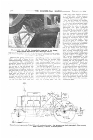
From the sliding pinion shaft, the motion is transmitted to a second cross shaft, which is connected by means of a short universally-jointed shaft with a floating pinion shaft. The latter is carried within the finaldrive casing that is mounted on the back axle, the final-drive gears being of double-helical pattern and substantial proportions. This final-drive casing is anchored by means of a short rod, as shown in the line drawing rem;•xlitced on the next page, and the length and disposition of this anchor rod is such as to insure that, in spite of the vertical rise and fall of he axle, the centre of the floating shaft remains constant, as near as possible, in relation to the centre of the spur-wheel shaft to which it is ilniversally jointed. This form of drive has been one of the features of Thornycroft's vehicles since its early steam-wagon days, and it was fully described and illustrated in our issue of the 21st March, Incr.
The differential gear is enclosed within the same casing as the final drive, and a differential locking gear is also fitted; this may be brought into operation by means of a lever situated behind the driver's seat. The rear-axle spring suspension is rather novel, and is shown in the general-arrangement drawing which we reproduce. The semi-elliptical springs are pivoted on the frame, so that their forward ends bear on the flat top face of the axle boxes, and the rear ends are supported, by substantial bolts, to brackets secured to the after ends of the side members of the main frame. By the aid of these bolts, the amount of rise and fall of the axle may be adjusted. The forward part of the tractor is supported by a single transverse spring over the front axle, both axle and
spring being carried in a heavy casting which forms the steering turntable. The steering gear is of the usual traction-engine type, with a worm-driven cross shaft to which the steering chains are secured.
The two side members of the main frame are formed' of straight pieces of steel plate, 12 inches wide by an inch thick, and these are suitably stayed and braced by means of stout steel angles and channels. All the wheels are of the traction-engine type, with cast naves and steel spdkes ; the leaders are 3 feet 6 inches in diameter by 8 inches wide, and the
'rivers are 5 feet 8 inches in diameter ny 12 inches wide. All the tires are pnwided with steel stropes, in accordance with the exemptions allowed.
Two sets of brakes are provided, and one of these, which is operated by a foot lever, acts on a brake drum, which is mounted on the countershaft, whilst the other—of the traction-engine type, with substantial shoes bearing on the inside of the rims of the driving wheels--is screw operated. The whole of the working parts are completely protected from dust and grit by substantial sheet-. metal covers; these are hinged to fixed portions on the chassis, and are held closed by stout spring hooks. Every part of the gear is, therefore, well rgotected, and, at the same time, quite accessible for the purpose of examination, or for making adjustments.
Many of the details in the construction of this tractor have been amply proved by lengthy experience with about a dozen machines of the same type, but rather smaller build ; some of these are fitted with dynamos and complete outfits for searchlight work. The general arrangement of the whole of the mechanism has been most carefully thought out, and, considering the size and power of the tractor, it is particularly handy and easy of manipulation. Its weight, with tanks empty, is well under the six tons allowed by the specification of the War Department. Of course, the employment of such a machine by civilian users would not he permitted by the regulations of the Heavy Motor Car Order, but we see no reason why the design should not be readily modified so as to make it a legal machine for use in this country for other than military purposes.