


Two-stroke-engine Braking
Page 46
If you've noticed an error in this article please click here to report it so we can fix it.
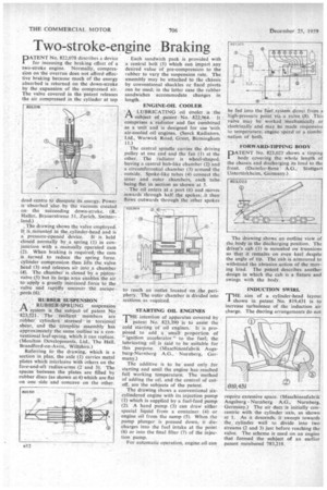
ATENT No. 822,078 describes a device for inceasing the braking effect of a two-stroke engine. Normally, compression on the overrun does not afford effective braking because much of the energy absorbed is returned on the down-stroke by the expansion of the compressed air. The valve covered in the patent releases the air compressed in the cylinder at top
dead centre to dissipate its energy. Power is absorbed -also by the vacuum created on the succeeding down-stroke. (R. Haller, Brauerstrasse 51, Zurich, Switzerland.) , The drawing shows the valve employed: It is mounted in the cylinder-head and is apressure-opened device. -It is held • closed normally by a spring (1) in conjunction with a manually operated cam (2). When braking is required,-the cam is turned to reduce the spring force. cylinder compression then lifts the, valve head (3) and releases air into a chamber (4). The chamber is closed by a pistonvalve (5) but its large area enable the air to apply a greatly increased .force to the valve and rapidly uncover the escape. pores (6).
RUBBER SUSPENSION ,
A _ RUBBER-SPRUNG suspension .rt system is the subject of patent No 823,521. The resilientmembers 'are rubber cylinders stressed in torsional shear, and the complete assembly his approximately the same outline as a conventional leaf-spring, which it can replace. (Moulton Developments, Ltd., The Hall, Brandford-on-Avon, Wiltshire.) Referring to the drawing, which is a section in plan, the axle (1) carries metal plates which interleave with others on the fore-and-aft radius-arms (2 and 3). The spaces between the plates are filled by rubber discs (as shown at 4)which are flat on one side and concave on the other.
Each sandwich pack is provided with a central bolt (5) which can impart any desired value of pre-compression to the rubber to vary the suspension rate. The assembly may be attached to the chassis by conventional shackles or fixed pivots can be used; in the latter case the rubber sandwiches accommodate changes in length.
ENGINE-OIL COOLER.
A LUBRICATING :oil cooler . is the 1-1 subject of patent No. 822,964. It comprises a radiator and fan combined as a unit and is designed for use 'with air-cooled oil engines. (Serck Radiators, Ltd., Warwick Road, Greet, Birmingham 11..)
The central spindle carries the driving pulley at one end and the fan (1) at the other. The radiator is wheel-shaped, having a central hub-like chamber (2) and a circumferential chamber (3) around the outside. Spoke-like tubes (4) connect the inner and outer chambers, each tube being flat in section as shown at 5.
The oil enters at a port (6) and moves inwards through half the spokes; it then flows outwards through the other spokes to reach an outlet located on ,the periphery. The outer chamber is divided into sections as required.
STARTING OIL ENGINES
'THE intention of apParatus covered by I patent No. 823,390 is to assist the cold starting of oil engines. It is proposed to add a smallproportion of "ignition accelerator" to the fuel; the lubricating oil is said to be suitable for this purpose. (Maschinenfabrik Augsburg-Nurnberg A.G., Nurnberg, Germany.)
The additive is to be used only for starting and until the engine has reached full working temperature. The method of adding the oil, and the control of cutoff, are the subjects of the patent.
The drawing shows a conventional sixcylindered engine with its injection pump (1) which is supplied by a fuel-feed pump (2). A hand pump (3) can dravi either special liquid from a container (4) or engine oil from the sump (5). When the pump plunger is pressed down, it discharges into the fuel intake at the point (6) or into the final filter (7) of the injection' pump.
For automatic operation, engine oil can
be fed into the fuel system direct from.a high-pressure pOint via a valve (8).-This valve may be worked mechanically. or, "electrically and rimy be made responsive to temperature, engine speed or a cbt-nbination of both.
FORWARD-TIPPING BODY
D ATENT No. 823,023 shows a tipping
body covering the whole length of the chassis and discharging its load to the front. (Daimler-Benz A.G., Stuttgart Untertiirkheim, Germany.) The drawing shows an outline view of the body in the discharging position. The driver's cab (1) is mounted on trunnions so that it remains on even keel despite the angle of tip. The cab is armoured to withstand the abrasive action of the moving load. The patent describes another design in which the cab is a fixture and swings with the body.
INDUCTION SWIRL
'THE aim of a cylinder-head layout I shown in patent No. 819,431 is to increase turbulence of the induction air charge. The ducting arrangements do not require excessive space. (Maschinenfabrik Augsburg Nurnberg A.G., 'Nurnberg, Germany.) The air duet 'is initially concentric with the cylinder 'axis, as shown at 1. As it descends, it sweeps towards the_ cylinder. wall to divide into two streams (2 and 3) just before reaching the valve. The scheme is used on an engine that formed the subject of an earlier patent numbered 783,218.