How the Hobbs Transmission Works
Page 41

Page 42

If you've noticed an error in this article please click here to report it so we can fix it.
HYDRAULICALLY controlled wet-plate clutches and torque reaction brakes are features of the four-speed planetary gearbox designed by Hobbs Transmission, Ltd., Leamington Spa, which is fitted to the Dennis Dominant range of passenger vehicles. A single quadrant lever, actuating a valve, is the only control required for gear changing and. whilst an overniding device is linked to a pedal in the clutch position, normal clutch operation is fully automatic.
The smooth take-up of the friction elements is such that the driver may change gear up or down with the throttle fully open, and the clutch-transfer sequence does not permit the engine speed to increase appreciably above that required in the gear being engaged. As the engine speed is reduced to idling, the clutch in use is automatically disengaged, but the engine may be started by towing or on the overrun.
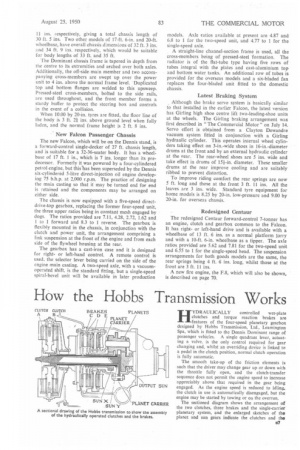
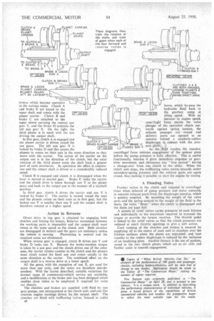
The sectioned diagram shows the arrangement of the two clutches, three brakes and the single-carrier planetary system, and the enlarged sketches of the planet and sun gears indicate the clutches and the
brakes which become operative in the various ratios. Clutch A and brake E are keyed to the input shaft and rotate with the planet carrier. Clutch B and brake C are attached to the input sleeve carrying the central sun gear Y, and the brake D controls the left sun gear X. On the right, the third planet is in mesh with the sun driving the output shaft.
In first gear, clutch A is engaged and CLUTC A the planet carrier is driven round the H E locked by brake D and this causes the LILGELEJ planets to rotate on their axis in the same direction as they move with the carrier. The action of the carrier on the output sun is in the direction of the clutch, but the axial rotation of the third planet turns the shaft back a greater part of each revolution. In operation the effect is continuous and the output shaft is driven at a considerably reduced speed.
Clutch B is engaged and clutch A is disengaged when the lever is moved to second gear. Brake E locks the carrier and the clutch drive is taken through sun Y to the planet gears and back to the output sun in the manner of a layshaft gearbox.
In third gear, clutch A drives the carrier and sun Y is locked by brake C. The carrier is turned round the suns and the planets rotate on their axes as in first gear, but the locked sun Y is smaller than sun X and the output shaft is therefore rotated at a higher speed.
Action in Reverse Direct drive in top gear is obtained by engaging both clutches and freeing the brakes. Relative movement between the working parts is impossible and the output shaft must rotate at the same speed as the clutch unit. Both clutches are disengaged in neutral and the gears are stationary unless
the vehicle is moving Planetating in neutral and the resultant noise are eliminated.
When reverse gear is engaged, clutch B drives sun Y and brake D locks sun X. Because the brake-reaction torque is taken by a sun gear and the clutch drives one of the other suns, the carrier rotates counter to the clutch and the planets must climb round the fixed sun and rotate axially in the same direction as the carrier. The combined effect on the output shaft is a reverse drive at a lower speed.
All the gears, with the exception of sun X, are used for more than one ratio, and the ratios are therefore interdependent. With the layout described, suitable variations for normal types of commercial-vehicle service are available, and a modification to the brake unit has been designed which enables close ratios to be employed if required for some car chassis.
The Clutches and brakes are supplied with fluid by two gear pumps, one incorporated in the clutch unit; anclone (for overrun engine starting) driven by the Output shaft. The clutches are fitted with trafficating valves, housed in radial all bores, which by-pass the hydraulic fluid back to ITOP GEARI the gearbox sump at idling speed. With an increase in engine speed, centrluial force moves the valve plunger of the operative clutch outwards against spring tension, the exhaust passages are ' closed and delivery ports are opened to an annulus behind a synthetic-rubber diaphragm in contact with the pressure plate.
As the fluid reaches the annulus, centrifugal force initiates engagement of the spinner plate before the pump pressure is fully effective. This is useful functionally, because it gives immediate response to gearlever movement and eliminates any "free period-" during a change-over from one clutch to the other. When the clutch unit. stops, the trafficating valve moves inwards under secondary-spring pressure and the exhaust ports are again closed, thus making it possible to start the engine by towing
A Floating Valve
Further valves in the clutch unit respond to centrifugal force when relieved of pump pressure and move outwards to uncover exhaust ports from the diaphragm annulus, which is quickly emptied. By matching the weight of the valve parts and the spring tension to the weight of the fluid in the ducts, the valve "floats" when the clutch is disengaged and the ducts are kept full.
A system of relief valves varies pressures of each friction unit individually to the maximum required to transmit the torque or provide the torque reaction. The throttle pedal is linked to the relief valves so that the clutch pressures are reduced at small throttle openings to give a soft action.
Cool running of the clutches and brakes is ensured by supplying oil to the centre of each unit to circulate over the friction surfaces when the plates are separated; and beat transfer to the rubber diaphragm is reduced by the inclusion of an insulating plate Another feature is the use of pockets, cored in the rear clutch plates, which act as air cells and further assist in smooth engagement.


