


nis Range Includes ngined Chassis
Page 39
Page 38
Page 40
Page 41
If you've noticed an error in this article please click here to report it so we can fix it.
New Underfloor engined Single-decker Available with Normally Aspirated or Supercharged Oil Engine and Semi-automatic Hydraulic Transmission System
EXCLUSIVE details of a new Dennis underfloorengined passenger chassis were given in "The Commercial Motor" on February 24, when it was stated that the new model would be completed in time to be exhibited at Earls Court. The Dennis Dominant, as it is known, has now materialized into a range of buses and coaches, designed for home and overseas re
quirements. A representative selection will be shown , and demonstrated at the Commercial Motor Show, where a new Falcon passenger model and a new version of the Centaur 7-tonner will also be seen.
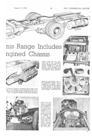
Basically, the Dominant range comprises short-, mediumand long-wheelbase 8-ft.-wide single-deckers for the overseas market, and a 16-ft. 9-in.-wheelbase chassis of 7-ft. 6-in. or 8-ft. width for home use. A horizontal version of the Dennis 0.6 oil engine, with or without supercharger, is the power unit. A semi-automatic four-speed transmission system, manufactured under licence from Hobbs Transmission, Ltd., is standard, and a double-reduction spiral-bevel or an Eaton two-speed assembly are alternatives in the final drive to the rear wheels. , In adapting the Dennis engine to a horizontal form, a re-arrangement has been required in the drive to the auxiliaries, and a new half-casting has been provided for the cylinder block to remove the bulge in the timing case at the flywheel end of the unit. This, of course, is necessary to reduce the depth of the engine under the off-side frame member, and helps to keep the floor level low. .
Although the engine timing arrangements are still at the rear of the unit, a new gear case is provided at the front of the crankshaft to drive the fan and dynamo. Like the camshaft drive, the auxiliaries are operated
154 ,
through helical gears from the crankshaft, and the whole auxiliary gear train at the front has a spring-loaden drive. Both ends of the camshaft are machined to drive the brake compressor or exhauster motor at the front, and the fuel pump at the opposite end.
Minor modifications to the lubricating system include a redesigned sump and suction pipe, and oil troughs, attached to the valve covers, which are fed from the rocker shaft and supply lubricant to the ball ends by gravity. Formerly the air-induction system was incorporated in the valve covers, but in the flat engine,,, air is supplied to the side of the heads and the same porting is used.
Apart from these alterations, the engine remains basically similar to the vertical unit. It has a bore and stroke of 105 mm. and 146 mm. respectively, the piston-swept volume being 7.585 litres. An output of 100 b.h.p. is developed at 1,800 r.p.m. in its normally aspirated form. In the blown engine, the compression ratio is lowered from 15 to 14 to 1, and-the output raised to 130 b.h.p. at the governed speed. Torque available at 1,000 r.p.m is 320 lb.-ft. for the standard engine, and 420 lb.-ft for the blown version.
The supercharger is driven from the auxiliary gears at the front of the engine, and revolving at If times engine speed, gives a maximum boost pressure of 6 lb per sq. in. It is protected from damage by rapid accelera ton or deceleration by an integral clutch.
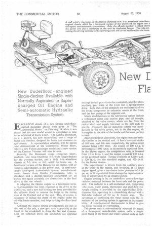
Engine cooling is by an underfloor contra-flow-type radiator mounted between the front axle and the power unit. The radiator is a self-contained unit, comprising tube stack, water pump, thermostat and axial-flow fan Ample cooling is provided by the eight-bladed 20-in.diameter fan, operating in a close-fitting shroud with a Still-tube radiator of 2.8 sq. ft. frontal area. The advantage of combining the water pump with the remainder of the cooling system is apparent in its accessibility. A remote-control thermometer is fitted to give the driver warning of overheating.
The power unit is conventionally mounted by means of a three-point semi-flexible system, with a singlepoint fixing at the front and widely spaced units at each side of the clutch housing. The right-hand securing point is outrigged from the frame. The engine is mounted in conjunction with the Hobbs transmission system, which comprises the clutches and gearbox complete. The Hobbs transmission, in its original form, was described in "The Commercial Motor" on November 11, 1947, since when a number of slight modifications has been incorporated.
The Hobbs transmission and its operation are described separately at the end of this article. For the Dennis chassis, the quadrant selector lever is attached to the control panel and although normally the transmission system does not include a separate clutch, the Dominant has an over-riding button to reduce the pressure on the clutches for shunting or in an emergency. The gear ratios are 1.0, 1.62, 2.62 and 4.72 to 1 forward, and 5.01 to 1 reverse.
A short propeller shaft, with Hardy Spicer couplings, transmits th.: drive to the rear axle. For the home models the unblown. engine is recommended for use in conjunction with a two-speed. axle having ratios of 5.14 and 7 to 1, or 5.57 and 7.60 to I. The control of the two-speed axle can be arranged to give, together with the transmission, five forward speeds, or to afford two distinct speeds for each of the four gearbox ratios (a total of eight). The shift is electrically controlled.
Single-speed Axle for Overseas The-single-speed double-reduction axle is advocated for overseas service, because it increases the ground clearance from 11 ins. to 12 ins. The single-speed axle has a bevel drive to the differential, and a doublereduction drive at the wheel hubs. This reduces the torque on the axle shafts and affords a higher overall efficiency in the transmission system. The supercharged engine is available primarily for these overseas models.
The home operator has the choice of Clayton Dewandre compressed-air or vacuum braking systems, but the compressed-air system is standard for overseas vehicles. The front brake drums are 16 ins. in diameter and 4 ins. wide. A brake-drum diameter of 154 ins, is specified for the rear wheels, this smaller drum improving the cooling of the braking system and helping to prevent tyre overheating in city service. All shoes are operated by a straightforward cam arrangement.
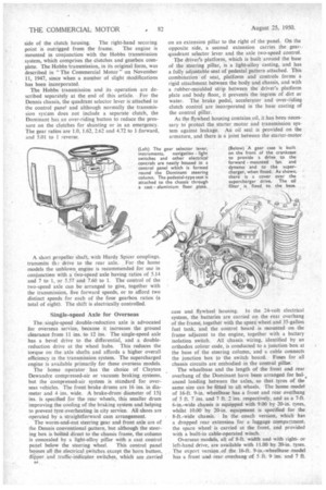
. The worm-and-nut steering gear and front axle are of the Dennis conventional pattern, but although the steering box is bolted direct to the chassis frame, the column is concealed by a light-alloy pillar with a cast control panel below the steering wheel. This control panel houses all the electrical switches except the horn button, dipper and traffic-indicator switches,, which are .Carried
n.
on an extension pillar to the right of the panel. On the opposite side, a second extension carries the gearquadrant selector lever and the axle two-speed control.
The driver's platform, which is built around the base of the steering pillar, is a light-alloy casting, and has a fully adjustable seat of pedestal pattern attached. This combination of seat, platform and controls forms a rigid attachment between the body and chassis, and with a rubber-moulded strip between the driver's platform plate and body floor, it prevents the ingress of dirt or water. The brake pedal, accelerator and over-riding clutch control are incorporated in the base casting of the control pillar.
As the flywheel housing contains oil, it has been necessary to protect the starter motor and transmission system against leakage. An oil seal is provided on the armature, and there is a joint between the starter-motor case and flywheel housing. In the system, the batteries are carried on the rear overhang of the frame, together with the spare wheel and 35-gallon fuel tank, and the control board is mounted on the frame adjacent to the engine, together with a battery isolation switch. All chassis wiring, identified by an orthodox colour code, is conducted to a junction box at the base of the steering column, and a cable connects the junction box to the switch board. Fuses for all chassis circuits are embodied in the control pillar.
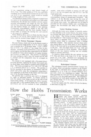
The wheelbase and the length of the front and rear overhang of the Dominant have been arranged for bal-, anced loading between the axles, so that tyres of the same size can be fitted to all wheels. The home model of 16-ft. 9-in, wheelbase has a front and rear overhang of 5 ft. 7 ins. and 7 ft. 2 ins, respectively, and as a 7-ft. 6-in.-wide chassis is equipped with 9.00 by 20-in. tyres, whilst 10.00 by 20-in, equipment is specified for the 8-ft.-wide chassis. In the coach version, which has a dropped rear extension for a luggage compartment, the spare wheel is carried at the front, and provided with a built-in cable-operated winch.
Overseas models, all of 8-ft. width and with rightor left-hand drive, are available with 11.00 by 20-in. tyres. The export version of the 16-ft. 9-in.-wheelbase model has a front and rear overhang of 5 ft. 9 ins. and 7 ft.
24-volt electrical 11 ins. respectively, giving a total chassis length of 30 ft. 5 ins. Two other models of 17-ft. 6-in. and 20-ft. wheelbase, have overall chassis dimensions of 32 ft. 3 ins. and 34 ft. 9 ins, respectively, which would be suitable for body lengths of 33 ft. and 35 ft.
The Dominant chassis frame is tapered in depth from the centre to its extremities and arched over both axles. Additionally, the off-side main member and two accompanying cross-members are swept up over the power unit to 4 ins, above the normal frame level. Duplicated top and bottom flanges are welded to this upsweep. Pressed-steel cross-members, bolted to the side rails, are used throughout, and the front member forms a sturdy buffer to protect the steering box and controls in the event of a collision.
When 10.00 by 20-in. tyres are fitted, the floor line of the body is 3 ft. 2ft ins, above ground level when fully laden, and the normal frame height is 2 ft. 8 ins.
New Falcon Passenger Chassis The new Falcon, which will be on the Dennis stand, is a forward-control single-decker of 27 ft. chassis length, and is suitable for a 32-36-seater body. It has a wheelbase of 17 ft. 1 in., which is 7 ins, longer than its predecessor. Formerly it was powered by a four-cylindered petrol engine, but thislas been superseded by the Dennis six-cylindered 5-litre direct-injection oil engine developing 75 b.h.p. at 2,000 r.p.m. The practice of designing the main casting so that it may be turned end for end is retained and the components may be arranged on either side.
The chassis is now equipped with a five-speed directdrive-top gearbox, replacing the former four-speed unit, the three upper ratios being in constant mesh engaged by dogs. The ratios provided are 7.11, 4.28, 2.72, 1.62 and 1 to 1 forward and 8.3 to 1 reverse. The gearbox is flexibly mounted in the chassis, in conjunction with the clutch and power unit, the arrangement comprising a link suspension at the front of the engine and from each side of the flywheel housing at the rear.
The gearbox has a cast-iron case and it is designed for rightor left-hand control. A remote control is used, the selector lever being carried on the side of the engine main casting. A two-speed axle, with a vacuumoperated shift, is the standard fitting, but a single-speed spiral-bevel unit will be available in later production
models. Axle ratios available at present are 4.87 and 6.8 to 1 for the two-speed unit, and 4.77 to 1 for the single-speed axle.
A straight-line channel-section frame is used, all the cross-members being of pressed-steel 'formation. The radiator is of the flat-tube type having five rows of tubes integral with the plates and cast-aluminium top and bottom water tanks. An additional row of tubes is provided for the overseas models and a six-bladed fan replaces the four-bladed unit fitted to the domestic chassis.
Latest Braking System Although the brake servo system is basically similar to that installed in the earlier Falcon, the latest version has Girling high shoe centre lift two-leading-shoe units at the wheels. The Girling braking arrangement was first described in "The Commercial Motor" on July 14. Servo effort is obtained from a Clayton Dewandre vacuum system fitted in conjunction with a Girling hydraulic cylinder. This operates internal wheel cylinders taking effect on 3-in.-wide shoes in 16-in.-diameter drums at the front and by an external hydraulic cylinder at the rear. The rear-wheel shoes are 5 ins, wide and take effect in drums of 15i-in. diameter. These smaller drums at the rear improve cooling and are suitably ribbed to prevent distortion.
To improve riding comfort the rear springs are now 5 ft. long and those at the front 3 ft. 11 ins. All the leaves are 3 ins. wide. Standard tyre equipment for home models is 8.25 by 20-in, low-pressure and 9.00 by 20-in, for overseas chassis.
Redesigned Centaur The redesigned Centaur forward-control 7-tonner has an engine, clutch and gearbox common to the Falcon. It has rightor left-hand drive and is available with a wheelbase of 13 ft. 6 ins, as a normal platform lorry and with a 10-ft. 6-in, wheelbase as a tipper. The axle ratios provided are 5.62 and 7.81 for the two-speed unit and 6.55 to 1 for the single-speed head. The suspension arrangements for both goods models are the same, the rear springs being 4 ft. 6 ins, long, whilst those at the front are 3 ft. 11 ins.
A new fire engine, the F.8, which will also be shown, is described on page 70.