


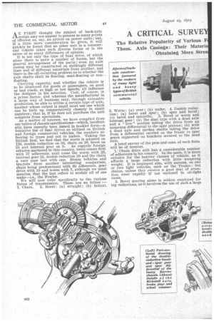
A CRITICAL SURVE ACK-AXLE DESIGN.
Page 14
Page 15
Page 16
Page 17
If you've noticed an error in this article please click here to report it so we can fix it.
AT FIRST thought the subject of back-axle design may not appear to possess so many,points of iffterest as, say, an article on power units ; but, if a little more consideration be given, it will quickly be found that no other unit in a commercial vehicle takes such diverse forms or is the cause of so many differences of opinion.
It is not only the type of final drive, of which alone there is quite a number of forms, but the general arrangement of the parts ; 'even an axle casing may be constructed on strikingly different lines and of different materials from another, and there is the oft-recurring problem as to whether the axle shafts shall be floating, semi-floating or nonheating.
Carrying capacity, and whether the vehicle. is to be employed for goods or passengers, on good or bad roads, at high or low speeds, all influence the designer in his selection. Cost, of course, is a prime factor, and whereas the manufacturer in a large way of business may, through extensive production, be able to utilize a certain type of axle, another whose output is small must use one which can be built up comparatively cheaply in small numbers ; that is, if he does not purchase the unit complete from specialists.
As a matter of interest, we have compiled from our tables of chassis specifications—which, incidentally, have recently been issued in booklet form—a tentative list of final drives as utilized on British and foreign commercial vehicles, the numbers referring to types and not to makes. Taking the British first, we find that the worm is adopted on 150, double reduction on 34, chain on 28, bevel on 25 and internal gear on 9. As regards foreign vehicles marketed in this country, bevel comes first with 57 adherents, next come the worm with 28, internal gear 22, double reduction 20 and the chain a very poor last with one. Steam vehicles and tractors form another interesting comparison, chain being predominant with 69 adherents, gear drive with 10 and warm with 7, although we must mention that the last refers to models all of one make—i.e., the Fowler.
We will now refer specifically to the various forms of transmission. These are an follow : 1. Chain. 2. Bevel : (a) straight ; (b) helical. 3. Worm : (a) over ; (b) under. 4. Double reduction: (a) bevel and spur ; (b) spur and bevel ; (c) bevel and epicyclic. 5. Bevel or worm and internal gear : (a) the dual type with a dead axle and a " live " portion taking the drive from an unsprung differential to the spur pinions ; (b) with a dead axle and cardan shafts taking the drive from a differential carried on the frame to spur gears supported on brackets secured to the dead axle.
A brief survey of the pros and cons. of each form will be of interest.
1. Chain drive still has a considerable number of adherents in his country. In the main, it is more suitable for the heavier classes of vehicle, as it affords a large reduction with little unsprung weight. It is employed also, with success, on one or two light vehicles, such as the Trojan ; but chains, unless they receive a good deal of attention, wear rapidly if not enclosed in oil-tight cases.
-2. Bevel gearing alone is seldom employed for big reductions, as it involves the use of such a large crown wheel, or conversely, a pinion with but few teeth. A straight bevel is also somewhat noisy, but this is obviated in the helical form. With light classes of vehicle it is a very suitable drive, and in one heavy vehicle—the Saurer—very careful design and manufacture have enabled its use on vehicles hauling, with trailers, 11 tons. One secret of this is that the teeth of the bevel pinion, when under light load, make contact with those of the bevel wheel for a portion only of their length, but when under toad the slight spring of the pinion causes full-tooth contact.
,3. As is hown by the figures we have already given, the popularity of the worm gear is rapidly increasing. . It is still chiefly employed, however, in this country. Whether the worm should be of the over or under type is principally a matter of road clearance and platform height, but it makes a very efficient drive and provides a large recluetion without occupying great space. From the point of view of lubrication, the under-type worm is the better, as there is no tendency to run dry until the worm wheel raises the drained oil.
4. Double-reduction gear is being used with great success on a number of vehicles, and, in particular, on those types where slight humming of the gears is unimportant. In the main, the reduction is first through bevels and then by spur gears, and this appears to be a better arrangement than that In which the spur reduction comes first. In the Huck axle there is first a bevel reduction and then an enicyciic drive to the axle shafts, whilst In the 7-ton Renault the epicyclic reduction gear is embodied in the rear wheels ; this is, in our opinion, a better arrangement, as the whole of the axle, including the axle shafts, can then be of light build.
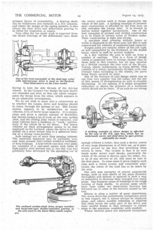
5. Internal-gear drive has not yet found many exponents in this country, but is being used on many foreign vehicles. It is a form which lends itself to the construction of a very light axle and in the obtaining of a low load-line, a striking example of this being the N.S.-type bus chassis. Other Vehicles in which this type of drive is Used with success are the Burford and Watson. Here, again, all the parts, so far as the final-drive gears, are relieved of much stress, and the differential with its .casing can be reduced to a size which looks almost absurdly small when compared with, say, a beVel-and-spur reduction gear. With a dead axle and cardan-shaft drive to the internal gears, the unsprung weight is reduced to what may be considered the minimum possible where an axle is employed (for there are designs in which the wheels are independent of an axle in the true sense of the word). There are only two British exponents of this drive—to wit, the Lacre and the G.W.K., but it is used with success on the Latil -incl the De Dion.
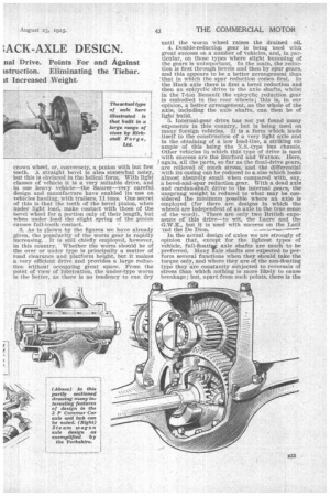
In the actual design of axles we are strongly of opinion that, except for the lightest types of vehicle, full-fLoatiut axle shafts are much to be _ preferred. Many Axle shafts are expected to perform several functions when they should take the torque only, and where they are of the non-floating type they are constantly subjected to reversals of stress than which nothing is more likely to cause breakage ; but, apart from such points, there is the primary factor of accessibility. A floating shaft can be withdrawn and replaced in a few minutes, and where the design of the casing permits, it also allows the final drive and differential gearing to be lifted for inspection or repair.
Very often far too much work is expected from the thrust bearings of the differential case, these having to take the side thrusts of the driving wheels. In the Commer Car design the axle shafts are extended and abut, so that one wheel compensates the thrust from the other, which appears to be an admirable arrangement.
We do not wish to enter into a controversy as to whether the torque, drive and braking should be taken through the springs or not. The former system appears to be satisfactory on many vehicles, even, of fairly large capacity. It is simple, clean and gives a certain amount of flexibility, but throws rather a lot of work on the rear caidan joint, and the sliding joint which is essential, and some vehicles have a•tendency to " buck," particu larly if the = clutch be at all fierce. For heavy vehicles an ideal arrangement seems to be that employed on the Leyland, where the drive is transmitted via a stout torque tube to a spherical bearing on a strong cross-member. , Axle casings are of more than passing interest. The materials employed may be malleable iron, cast steel, pressed steel (either welded or weldless), or drop forgings. A type which was once very popular consisted of a cast-steel centre with tubes of high-quality steel pressed into it, but this type has gradually been developed by the spreading out of the centre portion until it forms practically the whole of the axle. A striking example of pressedsteel construction is afforded by the Fiat axle, as this embodies the torque tube. It is formed in halves bolted together horizontally. One of the best examples of pressed and welded construction is to be found in certain axles of Timken make. Their construction is light and strong. A one-piece steel pressing without joints or welds is employed in the Moss axle, but this is only constructed for vehicles of moderate-load capacity.
Forged axles are usually either of the pot type, as well exemplified by the Kirkstall, or the double banjo, which is usen by several makers.
In a .few vehicles the axle is built up from a number of castings. This is a form of desigh which is employed more in foreign chassis than in those built In this country, but we may mention as a British example thereat axle of the 30-cwt. Vulcan, which, incidentally, is worm driven. This consists of a centre, horizontally divided, with cast trumpet tubes extending to the wheels, the parts being firmly secured by bolts.
One of the features of axle design which was at one time very popular was the tiebar, but the use of this means of strengthening an axle is steadily decreasing. In our opinion, it is either altogether redundant or shows the presence of a -weakness which should not be there. If an axle be not strong enough without a tiebar, then such a device, unless of very large dimensions, is of little use, as is practically proved by the fact that stretching often occurs in them. The trouble is that if an axle bends under severe road shocks, practically the whole of the stress is thrown upon the tiebar, for, to be of any service at all, this must be taut in the first place. In some cases it gives slightly, each time such a stress occurs, and eventually practically the whole of the load has to be taken by the axle.
One still sees examples of almost amateurish design, such as axle, shafts of the same diameter thronghout and splined or squared in such a way as materially to decrease their strengtlr over small areas. One frequent cause of breakage is the rough turning of these shafts. In several cases which have come under our observation fracture has followed one or other of the furrows caused by the tool.
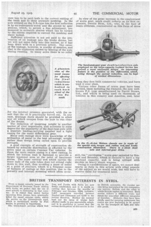
Silence is often a matter of great importance. The worm' drive has undoubtedly exceptional merit in this respect, but it cannot always be employed alone, and where another reduction is required this often forms the noisy part of the drive, and most careful design is then necessary to reduce noise to the minimum consistent with comfort.
Where internal gears are employed exceptional care has to he paid both to the correct cutting of the teeth and to their accurate meshing. In the axle utilized on the N.S.-type bus the first reduction is by an underneath worm and the second by spur pinions, which, to permit a fine, adjustment, are mounted in eccentric sleeves which can be turned to the extent required to correct the meshing and there locked.
Sufficient attention is not yet paid to the prevention of oil leakage into the brake drums, but we will not enter fully into this matter, as it has been dealt with in a previous article. One cause of the leakage, however, is worthy of mention, and that is the expansion caused by heating of the axle during running. In many axles there is no relief for the. internal pressure generated, with the result that the oil is practically forced out. In any case, drainage ducts should be provided to allow *any oil which escapes from the axle to run clear of the drums.
• The reduction of unsprung weight is another matter of vital importance, and accounts. to some degree for the popularity of the dual-type axle with a separate loading-carrying member and a light casing for the small differential gear.
Many axle casings show little knowledge of the' utilization of metal to the best advantage, weight rather than design being called upon to provide strength.
A good example of strength of construction obtained by scientific distribution Is afforded by the axles used on certain Commer Car vehicles. In these the main centre casing is a steel casting, in which the bottom wall is flattened to provide a larger tensional area at the point of maximum stress. The inner vertical web which carries the inner ends of the axle tubes does not extend right down to this wall, thus avoiding a mass of metal at a point of juncture, which is a frequent cause of failures of casings at this position, due to the porosity and internal stressing which often occur. In view of the great increase in the employment of worm gear, much credit reflect, on its first exponents, Dennis Bros., Ltd., who, in the face of mucli criticism, concentrated on this form of drive when they first built commercial vehicles, and have used it ever since.
Various other forms of worm gear have been devised, these including the Daimler, the now wellknown F.J. type manufactured by David Brown, Ltd., and which is being used on thousands of vehicles in this country and America, and, later still, the " enveloping " worm gear patented by Bostock and Bramley, which is claimed to have a big overload capacity, and is being utilized with success on heavy steam wagons.
Owing to considerations of space, we cannot deal nearly so fully, in this article with other aspects of the subject as we would wish, but will have to reserve these for treatment later.