


SAFETY IN BUS-DOOR CONTROL.
Page 11
Page 12
If you've noticed an error in this article please click here to report it so we can fix it.
An Ingenious American System in Which the Operation of Pneumatic Brakes Controls the Opening and Closing of the Passenger Doors.
ON ALMOST all forms of one-mancontrolled saloon bus the opening and closing of the door which serves as an entrance to and exit from the interior is under the control of the driver. This is satisfactory in most respects, providing the driver be punctilious in his duties, and the door completely encloses the steps. If both these provisions be met the passenger who wishes to alight and the intending traveller who wishes to board the vehicle are both prevented from doing so, and thereby taking unnecessary risks, while the bus is in motion.
The type of door, which is automatically operated by the driver, is certainly a valuable safety device when properly used ; bnt if it be opened before the vehicle is brought to a halt, possibly through the desire of the driver to redine the period of waiting at a stoppingplace, then its features of safety are negatived and accidents may result.
It is for this reason that we were particularly interested to read an article relating to the subject in our American contemporary, Automotive Industries, and, in view of the novelty of the arrangement therein described, we propose, for the benefit of our readers, extracting the main details, giving particulars of a means of door control which is interlocked with the pneumatic braking system. The idea has been developed by the Kansas City Railways, who, a short time ago, decided to employ a number of buses to augment the street-cal services which they maintain. The system is apparently particularly intended for use on buses with front and rear entrances, but it could be applied with equal efficiency to those of the one-mancontrolled pattern. It not only ensures that the doors remain closed until the brakes are set, but they must also be closed before the vehicle can start A further important point is that the bus to which the system is applied is auto
matically pulled up if the driver releases the steering wheel—a feature of paramount value if the driver should be incapacitated.
The Kansas City Railways have planned to run the buses on express lines, and to enable fast schedules to be adhered to they have arranged for passengers to board a vehicle at the front and alight from it at the• rear. It is to buses built to meet these requirements that the pneumatic system of door control has been applied. It is interconnected with the Westinghouse Pneumatic braking installations, the air for the system" being provided by a Westinghouse compressor of 6 cubic ft. output capacity, driven direct from the engine.
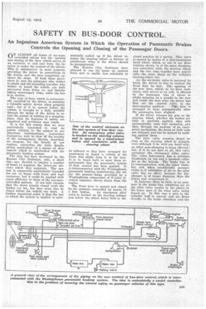
The front door is opened and closed by air pressure controlled by means of a foot button. An emergency pilot valve is located on the steering column just below the wheel, being held in the closed position by a spring. This valve is opened by means of a cast-aluminium hand wheel, which, as one df our illustrations shows, is of the same dim:deter, and concentric with, the steering wheel, and the two rims together have practically the same shape as the ordinary steering-wheel rim.
As the air-brake valve is operated by hand, the driver is free to control the front door by foot. The opening of the rear door, which, as we have indicated, only serves as an exit, is effected by the passenger who is about to alight stepping on a treadle in the step just inside the door after the driver has first set the control valve in the door-opening position. This door is arranged to close automatically after the passengers have alighted.
If the driver releases his grip on the steering wheel, whether the brakes are fully or partially applied, they will automatically come into operation, and then, through the medium of an emergency mechanism, the doors at both ends are released, and can be opened by pushing against them.
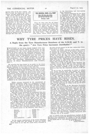
The pilot valve remains closed so long as the steering wheel is gripped, even although it be with one hand only, as when gear-changing is being effected; but, if it be not held at all, this valve energises the emergency relay valve. The valve last-named has a pressure diaphragm on top and a pressure cylinder at the bottom. The brake line is in communication with the upper chamber, and when considerable pressure exists in it admission of air to the pilot valve has no effect, because the diaphragm is of larger diameter than the piston and overpowers it.
If, however, there be little or no pressure in the brake line, admitting air to the pilot valve results in the piston in the lower part of the relay valve being forced up. In this way a port in the cylinder wall is opened, and air flows directly to the brake chambers and the
opening sides of the door engines. Air flows to both the brakes and the door engines through double-check valves. The device referred to as the door engine is used for opening the doors. The air on its way to the door engine has to pass through a relay valve with a diaphragm chamber, one side of which is connected to the brake line. The diaphragm acts upon an air valve, so that when there is pressure in the brake line the valve is opened and air can pass from the reservoir to the door engine, whereas an absence of air in the brake line (when the brakes are not in use) means that the doors cannot be opened as the air cannot get 'through this relay valve. From the relay valve the air passes to a different control valve for the door engine; the latter, has two co-axial plungers of different diameters. The chamber of the smaller plunger is connected to the reservoir line, whilst that of the larger plunger is connected to
the relay valve. The two plungers form piston valves, which admit air
to the door-closing and door-opening pipes respectively. The control mechanism for the doors is completed by a third valve, which is operated by foot and is connected in the line between the relay valve and the differential control valve. There is a similar valve in the line from the valve to the differential control valve on the rear door; this is operated by -means of the treadle on the rear step. The system maY appear to be somewhat complex, but a reference to the diagram of the piping which we reproduce will serve to indicate its method of application. We must acknowledge our indebtedness to Automotive Industries for the details which we publish.