


WORKSHOP WAYS RENAULT G170
Page 101
Page 102
Page 103
Page 104
If you've noticed an error in this article please click here to report it so we can fix it.
N Renault's G170 is in some ways a mixture of the old and the new. The new part is the electrical system where, if you do not know where to look, you can sometimes search for ages to find things like fuses and cutouts. Renault has grouped its electrics so that there are two main boxes containing almost all the electrical bits and pieces likely to give trouble. This makes it much easier to locate any electrical fault, as well as faults in the systems which the electrics monitor or control, and keeps the vulnerable switches and relays out of harm's way.
The "old" part of the design is really a return to some of the engineering practices which have been in danger of disappearing in the interests of progress, but not necessarily for the operator.
There is a much more widespread use of grease nipples than is the case with some other vehicles. There are still grease nipples on the propshaft universals, on the idler pulley for the compressor belts, and they have been added on the latest models to the bearings of the anti-roll bars both front and rear. There are sealed-forlife bearings, too, but only where Renault has found in practice that this life is a reasonable one.
There are, however, several points to watch. Mainly these are points of adjustment such as on the gearchange linkage, the clutch operating mechanism, the brake foot valve and so on. The adjustments -are quite simple, but for correct operation depend on measurements.
These measurements may not always be the same as on other Renault models with similar equipment, so consult the workshop manual — and to keep up-to-date with any service sheets from Renault as should the equipment suppliers change the measurements could well alter.
Our thanks go to the service staff of J Rawson (Trucks) of Longfield Road, Tunbridge Wells, Kent, for making a vehicle available and for sparing the time to go through its service points so comprehensively.
by Peter Wallage
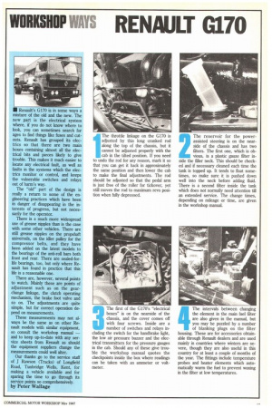
1 The throttle linkage on the G170 is adjusted by this long cranked rod along the top of the chassis, but it cannot be adjusted properly with the cab in the tilted position. If you need to undo the rod for any reason, mark it so that you can get it back in approximately the same position and then lower the cab to make the final adjustments. The rod should be adjusted so that the pedal arm is just free of the roller for tickover, yet still moves the rod to maximum revs position when fully depressed. 2 The reservoir for the powerassisted steering is on the nearside of the chassis and has two filters. The first one, which is obvious, is a plastic gauze filter inside the filler neck. This should be checked and if necessary cleaned each time the tank is topped up. It tends to float sometimes, so make sure it is pushed down well into the neck before adding fluid. There is a second filter inside the tank which does not normally need attention till an extended service. The change times, depending on mileage or time, are given in the workshop manual.
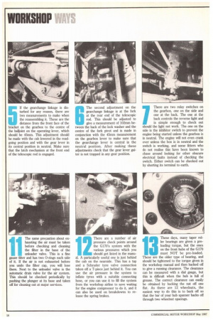
3 The first of the G170's "electrical boxes" is on the nearside of the chassis, and the cover comes off with four screws. Inside are a number of switches and relays including the switch for the handbrake light, the low air pressure buzzer and the electrical transmitters for the pressure gauges in the cab. Should any of these give trouble the workshop manual quotes the checkpoints inside the box where readings can be taken with an ammeter or voltmeter. 4 The intervals between changing the element in the main fuel filter are also given in the manual, but you may be puzzled by a number of blanking plugs on the filter housing. These are for accessories obtainable through Renault dealers and are used mainly in countries where winters are severe, though they are also useful in this country for at least a couple of months of the year. The fittings include temperature probes and heater elements which automatically warm the fuel to prevent waxing in the filter at low temperatures. 5 If the gearchange linkage is disturbed for any reason, there are two measurements to make when the reassembling it. These are the distance from the front face of the bracket on the gearbox to the centre of the balljoint on the operating lever, which should be 45mm. This adjustment should be made with the cab lowered in the roadgoing position and with the gear lever in its central position in neutral. Make sure that the latch mechanism at the front end of the telescopic rod is engaged. The second adjustment on the gearchange linkage is at the fork at the rear end of the telescopic rod. This should be adjusted to give a measurement of 102mm between the back of the lock washer and the centre of the fork pivot and is made in conjunction with the 45mm measurement on the gearbox lever to make sure that the gearchange lever is central in the neutral position. After making these adjustments check that the gear lever gaiter is not trapped in any gear position.
There are two relay switches on the gearbox, one on the side and one at the back. The one at the back controls the reverse light and is simple enough to check out should the light not work. The one on the side is the inhibitor switch to prevent the engine being started unless the gearbox is in neutral. The engine will not even crank over unless the box is in neutral and the switch is working, and some fitters who do not realise this have been known to chase around looking for other obscure electrical faults instead of checking the switch. Either switch can be checked out by shorting its terminal to earth.
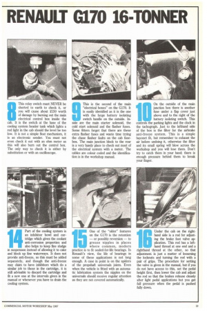
8 This relay switch must NEVER be shorted to earth to check it, or you will cause about £150 worth of damage by burning out the main electrical control box inside the cab. It is the switch at the base of the cooling system header tank which lights a red light in the cab should the level be too low. It is not a simple float mechanism, it is an electronic sender. You must not even check it out with an ohm meter as this will also burn out the control box. The only way to check it is either by substitution or with an oscilloscope. 9 This is the second of the main "electrical boxes" on the G170. It is easily identified as it is the one with the large battery isolating switch handle on the outside. Inside are the main starter solenoid, the cold start solenoid and the flasher fuses. Some fitters forget that there are these extra flasher fuses and waste time trying the chase flasher faults on the cab fusebox. The main junction block to the rear is a very handy place to check out most of the electrical system with a meter. The cables are colour coded and the identification is in the workshop manual.
On the outside of the main junction box there is another fuse under a flap cover just above and to the right of the battery isolating switch. This controls the parking lights and the clock in the tachograph. Just to the lefthand side of the box is the filter for the airbrake anti-freeze system. This is a simple bayonet fit, but remember to exhaust the air before undoing it, otherwise the filter and its small spring will blow across the workshop and you will lose them. Don't try to catch them in your hand; there is enough pressure behind them to break your finger.
11 The same precaution about ex
hausting the air must be taken before checking and cleaning the filter in the base of the unloader valve. This is a fine gauze fitter and has two 0-rings each side of it. If the air is not exhausted before you undo the filter cap, you will lose them. Next to the unloader valve is the automatic drain valve for the air system. This should be checked periodically by pushing the plunger at its base and taken off for cleaning out at major services. There are a number of air pressure check points around the G170's system with the various pressures which you should get listed in the manual. A particularly useful one is just behind the cab on the nearside. This has a tap and a Schrader tyre valve connection taken off a T-piece just behind it. You can use the air pressure in the system to inflate tyres with a suitable connecting hose, or you can use it to fill the system from the workshop airline to save waiting for the engine compressor to do it, and it can also be used on breakdowns to release the spring brakes.
These days, many taper roller bearings are given a preloading torque, but the ones on the front hubs of the G170 must NOT be pre-loaded. These are the older type of bearing, and should be tightened to the torque given in the workshop manual and then backed off to give a running clearance. The clearance can be measured with a dial gauge, but this is difficult when the hub is full of grease. The correct clearance can easily be obtained by backing the nut off one flat. As there are 12 wheelnuts, the easiest way to do this is to back off so that the bar of your hub spanner backs off through two wheelnut spacings.
1
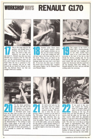
Part of the cooling system is an inhibitor bowl and cartridge which gives the coolant anti-corrosion properties and also helps to keep fine sludge m suspension instead of allowing it to cake and block up fine waterways. It does not provide anti-freeze, so this must be added separately, and though the anti-freeze may claim to have inhibitors which do a similar job to those in the cartridge, it is still advisable to discard the cartridge and fit a new one at the intervals given in the manual or whenever you have to drain the cooling system. One of the "older" features on the G170 is the retention — or possibly reversion — to grease nipples in places where common, modern practice is to fit sealed-for-life bearings. In Renault's view, the life of bearings in some of these applications is not long enough. A case in point is on the spiders of the propshaft universals joints. Even when the vehicle is fitted with an automatic lubrication system the nipples on the universals should receive regular attention as they are not covered automatically. Under the cab on the righthand side is a rod for adjusting the brake foot valve application. This rod has a lefthand thread at one end and a righthand thread at the other, so that adjustment is just a matter of loosening the locknuts and turning the rod with a pair of grips. The procedure for setting the valve is given in the manual, but if you do not have access to this, set the pedal height first, then lower the cab and adjust the rod so that the brakes release cleanly after light pedal applications but you get full pressure when the pedal is pushed fully down. This is the drain plug for the gearbox, and though there is nothing special about the plug, you need to take care whenever you drain the oil and renew it. Renault says that you must NEVER use a hypoid or EP oil. This will burn out the synchronising cones in the box, and if traces of one of these oils are found when the box is returned to Renault, your warranty will not be valid. Several oils are listed by Renault as suitable, but Rawson fitters say that any straight 30/40 oil is suitable. Another point where there are grease nipples which need regular attention are on the top and bottom bearings of the arms holding the antiroll bars both at the front and the rear of the truck. These were not fitted to the early versions of the G170, and the plastic bearings inside the arms had a very short life. If you have the older type of vehicle the newer type of bearing caps, complete with grease nipples, can be obtained from your Renault dealer. The engine of the G170 is fitted with a thermostatically controlled fan coupling, and on the older models there used to be a lock under this screwcap at the back of the fan so that should the thermo coupling fail, the fan would be turning all the time. Some operators locked this and never bothered to replace the thermostat with the result that the fan bearings failed after 500km, so Renault deleted the lock, and you will find nothing under the screwcap.
On the latest gearboxes with the 350 DR and 430 DB clutches, a new dutch linkage has been fitted. It is identified quite easily from the older type as there are no split pins on the device and there is a locating 1-plate to make sure the device fork is aligned properly. It has the extra advantage that you can adjust the setting without disconnecting it. The setting is made with a feeler gauge at the point on the linkage indicated here, and varies depending on the type of clutch and gearbox, so it is essential to consult the workshop manual. As well as the belts for the fan pulley, there is a double belt drive for the powerassisted steering. This also has to drive the air compressor which is mounted on the back of the PAS pump. These belts have to be adjusted fairly tight otherwise they are inclined to slip, and if they do they will wear the pulleys. There is a screw adjuster on the idler pulley, and as the bearing for this pulley is quite heavily loaded it is essential to keep it well lubricated. There is a grease nipple at the front of the pulley for this.
If you need to bar over the engine for timing, there is a pointer under a plate to the left of the bell housing at the top. Be careful when you take this plate off. Two screws hold the plate on, but there are other screws which hold the adjustable pointer. If you move these and the pointer shifts you will have to reset it at the TDC mark. The only way to do this is to bring the engine to approximately TDC, take the collet and spring off a valve, lower it on to the top of the piston and use a dial guage to get the exact TDC point. Remember to bring the engine to near TDC first or you may well lose the valve inside.