 1
1 2
2 3
3 4
4 5
5 6
6 7
7 8
8 9
9 10
10 11
11 12
12 13
13 14
14 15
15 16
16 17
17 18
18 19
19 20
20 21
21 22
22 23
23 24
24 25
25 26
26 27
27 28
28 29
29 30
30 31
31 32
32 33
33 34
34 35
35 36
36 37
37 38
38 39
39 40
40 41
41 42
42 43
43 44
44 45
45 46
46 47
47 48
48 49
49 50
50 51
51 52
52 53
53 54
54 55
55 56
56 57
57 58
58 59
59 60
60 61
61 62
62 63
63 64
64 65
65 66
66 67
67 68
68 69
69 70
70 71
71 72
72 73
73 74
74 75
75 76
76 77
77 78
78 79
79 80
80 81
81 82
82 83
83 84
84 85
85 86
86 87
87 88
88 89
89 90
90 91
91 92
92 93
93 94
94 95
95 96
96 97
97 98
98 99
99 100
100 101
101 102
102 103
103 104
104 105
105 106
106 107
107 108
108 109
109 110
110 111
111 112
112 113
113 114
114 115
115 116
116 117
117 118
118 119
119 120
120 121
121 122
122 123
123 124
124 125
125 126
126 127
127 128
128 129
129 130
130 131
131 132
132 133
133 134
134 135
135 136
136 137
137 138
138 139
139 140
140 141
141 142
142 143
143 144
144 145
145 146
146 147
147 148
148 149
149 150
150 151
151 152
152 153
153 154
154 155
155 156
156 157
157 158
158 159
159 160
160 161
161 162
162 163
163 164
164 165
165 166
166 167
167 168
168 169
169 170
170 171
171 172
172 173
173 174
174 175
175 176
176 177
177 178
178 179
179 180
180 181
181 182
182 183
183 184
184 185
185 186
186 187
187 188
188 189
189 190
190 191
191 192
192 193
193 194
194 195
195 196
196 197
197 198
198 199
199 200
200 201
201 202
202 203
203 204
204 205
205 206
206 207
207 208
208 209
209 210
210 211
211 212
212 213
213 214
214 215
215 216
216 217
217 218
218 219
219 220
220 MORE SPACE in
Page 86
Page 87
If you've noticed an error in this article please click here to report it so we can fix it.
NEW BEDFORD
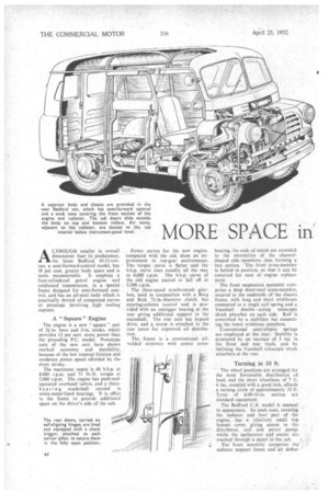
ALTHOUGH smaller in overall dimensions than its predecessor, the latest Bedford 10-12-cwt. van, a semi-forward-control model, has 18 per cent. greater body space and is more manoeuvrable. It employs a four-cylindered petrol engine and reinforced transmission, in a special frame designed for semi-forward control, and has an all-steel body which is practically devoid of compound curves or pressings involving high tooling expense.
A " Square " Engine
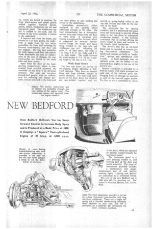
The engine is a new "square' unit of 3i-in. bore and 3-in, stroke, which provides 12 per cent. more power than the preceding P.C. model. Prototype tests of the new unit have shown marked economy and durability, because of the low internal friction and moderate piston speed afforded by the short stroke.
The maximum ouput is 40 b.h.p. at 4,000 r.p.m. and 71 lb.-ft. torque at 2,000 r.p.m. The engine has push-rodoperated overhead valves, and a three bearin g crankshaft carried in white-metal-lined bearings. It is offset in the frame to provide additional space on the driver's side of the cab. Power curves for the new engine, compared with the old, show an improvement in .top-gear performance. The torque curve is flatter and the b.h.p. curve rises steadily all the way to 4,000 r.p.m. The h.h.p. curve of the old engine started to fall off at 3,500 r.p.m.
The three-speed synchromesh gearbox, used in conjunction with a Borg and Beck 71-in.-diameter clutch, has steering-column control and is provided with an outrigger bearing at the rear giving additional support to the mainshaft. The rear axle has hypoid drive, and a scoop is attached to the rear cover for improved oil distribution.
The frame is a conventional allwelded structure with centre cross
bracing, the ends of which are extended to the extremities of the channelshaped side members, thus forming a • box section. The front cross-member is bolted in position, so that it can be removed for ease of engine replacement.
The front suspension assembly comprises a deep sheet-steel cross-member, secured to the underside of the chassis frame, with long and short wishbones _ connected to a single coil spring and a _ Vauxhall double acting telescopic shock absorber on each side. Roll is controlled by a stabilizer bar connecting the lower wishbone members.
Conventional semi-elliptic springs are employed at the rear.Stability is promoted by an increase of 3 ins, in the front and rear track, and by inclining the Vauxhall telescopic shock absorbers at the rear.
Turning in 33 ft.
The wheel positions are arranged for the most favourable distribution of load, and the short wheelbase of 7 ft. 6 ins., coupled with a good lock, affords a turning circle of approximately 33 ft. Tyres of 6.00-16-in. section are standard equipment.
The Bedford C.A. model is unusual in appearance. Its snub nose, covering the radiator and fore part• of the engine, has a relatively small top bonnet cover giving access to the distributor, coil and petrol pump, whilst the carburetter and starter are
reached through a panel in the cab 4 The front assembly comprises the radiator support frame and air deflec
tor, which are bolted in position, the front wheel-arches and splash guards welded together, footwell panels, scuttle, pillars, windscreen top rail and instrument panel. The windscreen top rail is welded to the roof, and the bottom of the front assembly is bolted to the underbody.
A separate unit from the frame, and secured to it at four points, the under. body is made from the two major assemblies, the front half including the forward cross-bearers, cab floor and seat support. The rear part comprises the body bearers and floor side panels. Made detachable for ease of replacement in the case of damage, the rear wheel-arches are bolted to the body sides and floor panels.
Apart from the floor of the loadcarrying compartment, which is constructed from proofed plywood, the remainder of the body is an all-metal structure. The sides are one-piece pressed-steel panels, with an embossment for stiffening and display purposes, and are attached to the front and rear door pillars by spot welding and bolted to the underfrarne.
Intermediate pressed-steel pillars insulated by felt packing afford additional strength in the sides. The load compartment has a corrugatedsection sheet-steel lining from the floor to waist level. A one-piece steel bracing is employed for the roof, which is supported on inverted top-hatsection hoops, the hoops and panel being welded to the cant-rails and windscreen top rail. Affording 135 cubic ft. of toad space, the body is '7 ft. long, 4 ft. 11 ins, wide, and 4 ft. I in. high inside. The width between the wheel-arches is 3 ft. 7i ins. Loading height at the rear is 2 ft. 110.
Wide Rear Doors
The two rear doors are carried en self-aligning hinges affording a fullwidth opening. They have an interior lining and large windows bedded in rubber channels. The inner arid outer panels of the front doors are clinched and spot-welded together, and are carried on spring-loaded rollers at the top and bottom and slide on the outside of the body.
The prototype has no opening windows, but it is understood that plans have now been made to provide sliding lights in the cab doors in subsequent production models. It was formerly considered that in normal driving the doors would be open and secured by the inbuilt check mechanism.
The driver's seat has an all-metal frame and is mounted on runners giving fore-and-aft adjustment. The squab and cushion are built on "snakewire" springs and upholstered with Vynide. A fixed passenger seat, an optional extra, can be bolted to the plywood floor slightly to the rear of the driver's seat.
Interior ventilation is provided by a built-in system with ducts arranged on each side of the radiator grille discharging fresh air through an aperture in each of the footwell upper panels. The flow of air is controlled by valves