


CROSSLEY BUILDS A SUPE :HARGED OILER
Page 44
Page 45
If you've noticed an error in this article please click here to report it so we can fix it.
Crossley 8.5 litre Blown Oil Engine Produces 138140 b.h.p. at 1,750 r.p.m. Interesting Vehicle in Production for Dutch State Railways
PLANNED to meet the special requirements of the Dutch State Railways, an interesting type of chassis, fitted with a supercharged power unit, is now, being produced by Crossley Motors, Ltd., Gorton, Manchester. This design is intended to carry a 48-seater body and to be used on fast inter-city services which cover long stretches of road without appreciable gradient.
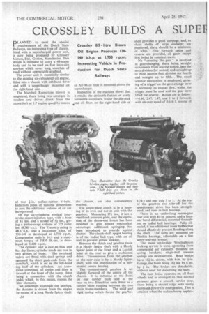
The power unit is essentially similar to the existing six-cylindered oil engine, fitted into a chassis with left-hand drive and with a supercharger mounted on the right-hand side.
The Marshall Roots-type blower is employed, there being two arranged in tandem and driven direct from the crankshaft at 1.7 engine speed by means
of two 1-in. endless-rubber V-belts. Induction pipes of suitable dimensions to pass the additional volume of air are incorporated.
Of the six-cylindered vertical fourstroke direct-injection type, with a bore of 41 ins, and a stroke of 51 ins., giving a piston-swept volume of 525 cubic ins. (8,589 c.c.). The Treasury rating is 48.6 h.p., and a maximum b.h.p. of 138-140 is developed at 1,750 r.p.m. Compression ratio is 14:1 and a maximum torque of 5,830 lb.-ins, is developed at 1,400 r.p.m.
The cylinder unit is cast en bloc and has dry liners; cylinder heads are cast in two groups of 'three. The overhead valves are fitted with dual springs and operated by short push-rods from the camshaft, which is set in the left-hand top half of the cylinders. An Auto lean combined oil cooler and filter is located at the front of the sump, there being a connection with the clutch pedal, which, by this means, rotates the liter elements.
Set amidships alongside the gearbox, the dynamo is driven from the engine by means of a long Hardy Spicer shaft; an Air-Maze filter is mounted above the supercharger.
Inspection Of the machine shows that it retains the desirable feature of easily accessible atomizers, whilst the dip-stick sand oil filter, on the right-hand side of
the chassis, are also conveniently reached.
The single-plate clutch is in a housing of its own and not in unit with the gearbox. Measuring 17i ins., it has a ventilated pressure plate, and the operation of the throw-out levers has been modified to give greater mechanical advantage; additional springing has been introduced to provide against. chatter. The clutch-shaft spigot bearing is of the radial ball type, with an cal seal to prevent grease' leakage.
Between the clutch and gearbox there is a Hardy Spicer shaft with a Hardy Spicer joint at the front and a Layrub joint at the rear to give a cushioned drive. Transmission from the gearbox to the rear axle is by a Hardy Spicer shaft, with the interposition of a substantial centre bearing.
The constant-mesh gearbox is set slightly forward of the centre of the chassis. It is mounted at the front on one rubber bush and at the rear on two Silentbloc units fitted to a carrier plate running between the two main frame-members. The solid an(,,I rigid casing which forms the gearbox shell provides a good sumpage, and, as short shafts of large diameter are employed, there should be a minimum of whip. Five forward ratios and reverse are provided, all gears except first being in constant mesh.
No "crossing the gate" is involved in gear-changing, there being straight movements from reverse to first, into the next division for second, and straight up to third, into the final division for fourth and straight up to fifth. The usual selector mechanism is employed; pressing of a trigger on the gear-change lever is necessary to engage first, whilst the trigger must be used and the gear lever lifted for reverse. Ratios are as follow: —4.46, 2.47, 1.47, and 1 to 1 forward, with an over speed of 0.656:1, reverse of 4.74:1 and rear axle 5 to I. At the rear of the gearbox the take-off for the speedometer drive has been strengthened, and runs in ball bearings.
There is an underslung worm-gear rear axle with 81-in centres, and a fourstar bevel differential, mounted throughout on 'radial ball bearings. Fully oilsealed, it has additional inner baffles that should effectively prevent flooding along the shaft. The hubs are mounted on Timkin bearings, adjustable on a fine screw-and-nut system.
The most up-to-date Westinghouse braking sys,em is used, operating from compressed air cylinders mounted on spring brackets; single-leaf tension springs are incorporated. Rear brakes have 161-in, drums, with 6-in, by fin. facings, the front being 161 ins. by 4 ins. by 1 in. The brakes are detachable, without need for disturbing the hubs.
The foot brake operates on all four wheels and is arranged so that normal pressure gives a smooth service stop, there being a second stage with vastly increased power for emergencies._ This is attained when the sudden heavy applica tion of the brake pedal brings a secondary lever into action.
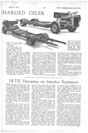
The front axle is a heavy drop forging with the taper-socket type of king-pin fitted in the axle beam; king-pins are specially hardened and have chromium-plated surfaces. ": Aparticularly sturdy track rod is employed. Rear tyres are 9.75-in. by• 20-in, low-pressure twins, with low-pressure 11.25-in. by 20-in. singles at-the front. Semi-elliptic springs are employed, those at the rear -being underslung., .As they are long and wide, good riding comfort shoidd result.
-Overall length of the chassis is 34 ft. 71 ins., with a wheelbase of 20 ft. 3i ins., front and rear overhangs being 4 ft. 2+ ins, and 10 ft. 2 ins. respectively. The cab unit is carried forward of the front axle and the radiator is designed to accommodate a full front. Main members of the frame measure 11 ins. by 31 ins, by in. at the deepest section and are cross-braced at eight points. Top and bottom flanges of the main frame are tied with wide bands at suitable points and the centre tubular cross-braces are strengthened by the addition of triangulated tubular braces to the frame. Stiffening brackets are also provided over the rear axle, and in general the construction is most robust.
The steering column is mounted as a separate.unit, and is connected to Marks double-roller gear. The inner lock turns through 43+ degrees and the outer lock through 33 degrees.
For brake, clutch, and throttle pedals, car layout has been adopted, whilst gear and brake levers are situated at the driver's right hand. In front of the driver there is an instrument panel with five coloured lights to indicate the operation of the various items of electrical equipment, together with tank and linepressure gauges, speedometer, and thermometer.
The electrical system is of C.A.V. make, operating from a combined box. An oil-pressure gauge is fitted directly to the engine, with tell-tale light on the instrument board.
This type of vehicle is likely to be one of the mainstays of the Dutch railways' road fleet in years to come.