


Patents Completed.
Page 20
If you've noticed an error in this article please click here to report it so we can fix it.
Complete specifications of the following patents will be sent to any address in the United Kingdom upon receipt of eightpence per copy at the Sale K.ranch, Patent Office, Holborn, W.C.
Follows the Parisian Guards.
G. 1. Biggs and G. Commander.—Nu. 7054, dated 21st March, 1911.—This specification describes a mudguard fur motor wheels which is formed in four pieces of L-section. The two sections on the inside of the wheel are fixed together by a nut and bolt at the top; the two parts forming the outer side are hinged together, and overlap the first pair, engaging with pins fixed on them. A rubber or leather flap is attached to the outer side to prevent lateral splashing of mud. The inner and outer halves are locked together by pins and springs at the lower corners.
A Straker Railcar Gearbox.
E. Clare and Straker and Squire, Ltd. —No. 11,138, dated 8th May, 1911.— This specification describes a changespeed mechanism which is capable of giving two or more speed ratios in either a forward or a backward direction, and which is also applicable to all classes of vehicles running on rails and propelled by internal-combustion engines. Three shafts are employed, having their axes parallel to each other, and mounted in suitable bearings in a gearbox. The two upper shafts—which are called driving shafts—have gear-wheels constantly in mesh with one another. The right-hand shaft is driven direct from the engine, and rotates in the same direction. The left-hand shaft is constantly rotating in the opposite direction. These two shafts carry gear-wheels which are movable
ongitudinally on the shafts, and are controlled by the levers arranged at each side of the gearbox. These gear-wheels engage with wheels fixed to the lower shaft from which the two wheel axles of the car are driven.
A Novel Starbing Handle.
M. Demonte.—No. 7760, dated 28th March, 1911.—This specification describes a starting-handle for internalcombustion engines; this is adapted to be thrown instantaneously and automatically out of gear, and so to prevent accident should the motor start backwards. A loose sleeve is fixed on the end of the engine-shaft, and this carries the starting-handle. A disc is fixed on the sleeve, and carries on its inner face a conical ring fitting in a similar groove on the face of the disc. A locking ring holds it in place. A number of links is (.onnected to this conical ring by ball ad socket joints. The other ends of the links are secured in similar manner to the plate fastened on to the frame of the engine. The sleeve is provided with a clutch face engaging a clutch on a sh.)rt sleeve secured to the engine-shaft. The links are so arranged that rotation of the starting-handle in the direction in which the engine is to run, causes the disc to be pulled in, and brings the clutch into engagement, so that the rotation is transmitted to the engine-shaft and the engine started. Should the engine start backwards for any reason, it would imniediately rotate the disc in the wrong
direction, and the angularity of the links would be increased so that the disc would be pushed away and the clutch disengaged. The action is instantaneous and automatic, so that it is impossible for anyone starting the engine to receive injury.
A Bosch Starting System.
Robert Bosch, Ltd.—N-.). 9840, dated under International Convention, 27th March, 1911.—This inven!ion has for its object to facilitate the starting of internal-combustion engines " on the spark." When a multi-cylinder engine is stopped through the ignition's being cut off, it finally settles down to reit with all cylinders on about the mid position, one of them being on the comvession and another on what would have been the explosion stroke, but whit h merely has a half-compressed charge of mixture in it. Under normal circumstances the first cylinder to be ignited in starting is that one which is on the compression stroke, as the other charged cylinder has passed the point of ignition. The present invention consists in ar anging that the charge in this second cylinder can be
ignited to start the engine. On the distributor an auxiliary brush is provided that is displaced through 90 degrees for
a four-cylinder engine, or an equivalent amount depending on the number of cylinders, and this brush is connected to an auxiliary magneto or other source of current. On supplying the current, this half-compressed charge is exploded and it is sufficient to drive the engine until the normal ignition can take place.
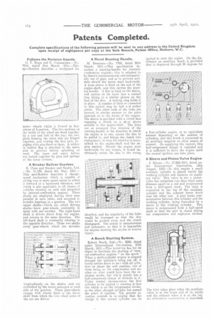
A Sleeve and Piston Valve Engine J. Miesse.—No. 17,804/1911, dated under International Convention, 12th August, 1910.—In this engine a small auxiliary cylinder is placed beside the working cylinder and contains an auxiliary valve. This valve is not a pistonvalve but comprises two discs fixed some distance apart on a rod and reciprocated from a half-speed shaft. The inlet is connected to the top of the auxiliary cylinder and the exhaust lower down near the other end. A port forms communication between this cylinder and the working cylinder, being controlled by a sleeve 3n the working cylinder. This sleeve is reciprocated from a half-speed shaft so that the port is closed during the compression and explosion strokes.
The inlet takes place when the auxiliary valve is at the lower end of its stroke and the exhaust when it is at the top. An alternative construction is described_