


British Airways starts the service of the Scania K112 with
Page 121
Page 122
Page 123
Page 124
If you've noticed an error in this article please click here to report it so we can fix it.
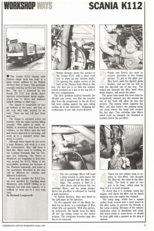
a short road test to show up any obvious faults. On opening the engine covers at the back of the Plaxton body fitted to this bus, the first job is to flick the isolator switch mounted on a box in the top left of the rear compartment.
The first problem noticed beneath the off-side rear cover, was that the transfer pipe from the compressor to the air dryer had been chafing against the pipe taking cooling air to the alternator. Strapping the cooling pipe to one side averts disaster. Fluids and filters are next to receive attention in the Scania service. To get to the glass prefilter bowl, undo the dipstick guide bracket, and use the fan belt to tuck the dip-stick out of the way. The nurled nut beneath the filter bowl often defies fingers, and needs the pliers.
The gauze tube inside the bowl must be scrupulously cleaned: any dirt around the rim of the bowl will allow air into the system. The casting which supports the filter, and also houses the priming pump can crack where the banjo bolt secures the fuel pipe. Two cartridge type filters which must be changed are mounted in tanidern below the pre-filter.
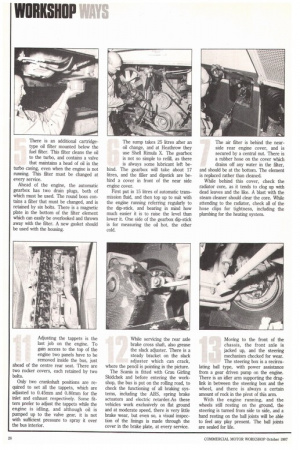
The two cartridge filters will need a strap wrench to undo them: the seal is integral with the filter cartridge. The system is bled to a valve above and between the two cartridge filters, and the pump plunger above the pre-filter is released by turning it anti-clockwise.
At British Airways, they also bleed to the spill pipes on the injectors.
On the opposite side of the block, behind the air-dryer, is a centrifugal oil filter which lifts out upwards. With this particular bodywork, the handle must be taken off the tap taking water to the heater system. The crankcase breather pipe also has to be removed. There are two rubber se.als to replace in this filter: one beiteath the filter lid, the other in the filter body. The body is spun by two jets in its base, which must be clear if it is to work properly.
To check that it is working, warm the engine, and check the filter can be heard spinning once the engine has stopped.
The sump plug, which has a square socket head, screws into a steel insert in the alloy sump, to prevent the threads in the sump wearing. Because of the relative expansion rates of aluminium and steel, this insert tends to come loose, so should be kept tight with a spanner as the plug is undone. There is an additional cartridgetype oil filter mounted below the fuel filter. This filter cleans the oil to the turbo, and contains a valve that maintains a head of oil in the turbo casing, even when the engine is not running. This filter must be changed at every service.
Ahead of the engine, the automatic gearbox has two drain plugs, both of which must be used. The round boss contains a filter that must be changed, and is retained by six bolts. There is a magnetic plate in the bottom of the filter element which can easily be overlooked and thrown away with the filter. A new gasket should be used with the housing. The sump takes 25 litres after an oil change, and at Heathrow they use Shell Rimula X. The gearbox is not so simple to refill, as there is always some lubricant left be hind. The gearbox will take about 17 litres, and the filler and dipstick are behind a cover in front of the near side engine cover.
First put in 15 litres of automatic transmission fluid, and then top up to suit with the engine running referring regularly to the dip-stick, and bearing in mind how much easier it is to raise the level than lower it. One side of the gearbox dip-stick is for measuring the oil hot, the other cold. The air filter is behind the nearside rear engine cover, and is secured by a central nut. There is a rubber hose on the cover which drains off any water in the filter, and should be at the bottom. The element is replaced rather than cleaned.
While behind this cover, check the radiator core, as it tends to clog up with dead leaves and the like. A blast with the steam cleaner should clear the core. While attending to the radiator, check all of the hose clips for tightness, including the plumbing for the heating system. The exhaust brake is triggered electronically by the brake pedal, as is the electric retarder built into the automatic gearbox. The exhaust brake itself is operated by a pneumatic cylinder which points upwards, and can fill with rain water. They have had trouble with the exhaust brake jamming and not coming on in operation, yet appearing to be free when the engine is not running.
Replacing the bushes cures the problem, and with the later type of bushes, the problem has not reappeared. The electric retarder which is inside the gearbox, is preset at the factory and requires no further attention. Beneath the bus, the alien bolts securing the prop-shaft flanges must be checked for tightness. The universal joints both have grease nipples, as has the sliding spline in the middle of the propshaft.
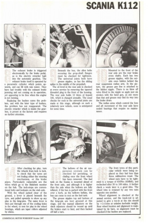
The oil level in the rear axle is checked at every service by removing the tapered threaded plug in the front of the housing. The rear axle holds 12 litres of hypoid 140, which is changed annually. The usual checks for rock in the universal joints are made at this stage, although on such a relatively new vehicle, none is anticipated for some time. Mounted to the front of the rear axle are the rear brake cross shafts. Each has two grease nipples, with the outside ones hidden behind the rear suspension radius arm. In the picture, the grease gun line is attached to the hidden nipple. There is no blow off valve fitted to the nipple so apply just six strokes with the hand gun, as any more than that and grease may find its way into the brake drum.
The radius arms which control the fore and aft movement of the rear axle have sealed bearings that require no maintenance.
Adjusting the tappets is the last job on the engine. To gain access to the top of the engine two panels have to be removed inside the bus, just ahead of the centre rear seat. There are two rocker covers, each retained by two bolts.
Only two crankshaft positions are required to set all the tappets, which are adjusted to 0.45mm and 0.80mm for the inlet and exhaust respectively. Some fitters prefer to adjust the tappets while the engine is idling, and although oil is pumped up to the valve gear, it is not with sufficient pressure to spray it over the bus interior. While servicing the rear axle brake cross shaft, also grease the slack adjuster. There is a steady bracket on the slack adjuster which can crack, where the pencil is pointing in the picture.
The Scania is fitted with Grau Girling Skidchek and before entering the workshop, the bus is put on the rolling road, to check the functioning of all braking systems, including the ABS, spring brake actuators and electric retarder.As these vehicles work exclusively on flat ground and at moderate speed, there is very little brake wear, but even so, a visual inspection of the linings is made through the cover in the brake plate, at every service. Moving to the front of the chassis, the front axle is jacked up, and the steering mechanism checked for wear. The steering box is a recircu lating ball type, with power assistance from a gear driven pump on the engine. There is an idler arm supporting the draglink in between the steering box and the wheel, and there is always a certain amount of rock in the pivot of this arm.
With the engine running, and the wheels still resting on the ground, the steering is turned from side to side, and a hand resting on the ball joints will be able to feel any play present. The ball joints are sealed for life. After checking for play, turn the wheels from lock to lock, to check that the tyres are not fouling either the steering mechanism, or the brake pipes. Particularly vulnerable are the wires which go to the Skidchek monitor on the hub. The lock-stops are conventional bolts and locknuts on the stub axle.
With the wheel jacked clear of the ground, a lever is placed beneath the tyre, and pulled upwards to show up any play in the king-pins. The same lever is then put through one of the cooling holes in the wheel, to test for play in the wheel bearings, which are taper rollers adjusted by shims. The bellows of the air suspension system can be checked for perishing, or chafing once the front wheel has been removed. The fuel tank on the Scania is mounted ahead of the front axle, and although it is higher than the axle when the bellows are fully inflated, if the bus is parked with the front over a kerb, as the bellows beflate, the bus can come to rest on the fuel tank.
The grease nipples top and bottom of the king-pin are best greased at this stage, and the manual adjusters on the slack adjusters should be wound up until the brakes start to bind, and then backed off half a turn.
The front tyres of this particular vehicle were being replaced as they had less than three millimetres tread. The wheel nuts have to be tight
ened to a torque of 610Nm (4501bft), and rechecked after 50 to 100 miles. A further check a week later is a good idea. The wheel trim is retained by any two nuts opposite one another.
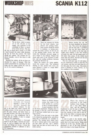
Wheel alignment is checked at the annual service, and the track-rod is adjusted to give a toe-in at the rim should be +1±1mm at unladen kerbside weight. Rear wheel location and alignment is maintained by tie bars, so alignment must be checked if the bushes are replaced. The air dryer, which is mounted on the off-side of the engine, just outboard of the centrifugal oil filter, is checked at every service. The simple way to check that it works, is to hold a hand beneath the outlet while discharging the air from the system. The hand should get soaked. The crystals are replaced annually, even if the dryer is still working.
Beneath the vehicle, all the air lines are checked for signs of damage. With the system pressurised by operating the foot brake and the engine turned off, cock an ear for the sound of leaking air. There are separate air circuits for the front wheels, rear wheels and parking brake. Each system should be tested in isolation, so having pressurised the entire system, let the air out of the parking brake circuit, and then watch the footbrake pressure guage to see if there is any leakage. Repeat this check with each of the systems in isolation, and any sealing problems between the systems will show up.
When the brakes are being applied, watch the acuator rods. The actuators sharing an axle should both move the same distance: if there is a large difference, there is a fault. Before leaving the cab, lift the hatch alongside the drivers seat This covers the batteries and the fuel tank. A problem that has left these buses in the lurch, is the sender in the fuel tank. Unlike most vehicles, if the wire breaks off inside the tank, the fuel guage goes to full rather than empty. If the vehicle has more than one driver, the fuel can run out before the fault is noticed.
The two cold start type 12 volt batteries are connected in series to feed the 24 volt system, and they are held down by a bar that grips the lower edge. Electrolyte level is checked at every service, as is the condition of the terminals.
The electrical control systems are housed beneath a cover on the off-side, beneath the drivers window. To the left is the black box which controls the braking system. At the top are the valves for the gear control, and below them is the bank of fuses. Not only is the electrical system on a bus complicated, but it must also be reliable, if only to comply with the PSV regulations.
Every service includes a thorough check of all the lights, internal and external, as well as making sure that all the seats and fittings are secure. A loose fire extinguisher bracket is sufficient to fail a PSV inspection.
Fitters at British Airways reckon that much of the work needed at a service is due to accident damage. A good example is this ear on the front suspension. Hanging close to the ground, it has hit a kerb and broken off. It had been welded back on at a previous service.
The front of the fuel tank is also liable to be clouted by passing kerbs, and all low slung bits of bodywork are carefully inspected. The heating ducts which carry hot air to various parts of the coach body can also chafe and fray, and a defunct heater unit can take as much work as an entire service. When the chassis is delivered to the body builders from Scania, it has a very short wheelbase, and the chassis is lengthened to suit the type of body. This means that the service cables running from the controls at the front to the engine at the rear follow a tortuous route, if the chassis is not extended to its full length.
A case in point is the throttle cable, which is nylon lined, and can become stiff, partly due to its extra curves. Being well tucked out of the way, throttle cable replacement is one of the least favourite jobs to be done to the Scalia K112 bus.