


FIRST BRITISH BUS vv th POWER TEERING
Page 56
Page 57
Page 58
If you've noticed an error in this article please click here to report it so we can fix it.
The seven-bearing crankshaft and cast-iron crankcase assembly have been designed to reduce torsional vibration to a minimum. To achieve this object, the crankshaft has been manufactured without balance weights and the timing gears are located at the flywheel end. With this arrangement the third harmonic does not occur in the operating speed range and a harmonic damper is not required,
The C.A.V. injection pump is driven through couplings tuned to give freedom from torsional'effects. Driven from the crankshaft through a train of alternate steel and alloy-iron gears. the camshaft runs in an oil bath situated high on the near side of he engine. The gears -are produced on a shaving machine and crowned to obviate high stress concentration.
Crankshaft main and big-end bearings are of copperlead alloy. The total main beating area is 56 sq. ins. and the total area of the big-ends 38.6 sq. ins.
Magnetic Lubrication Filters
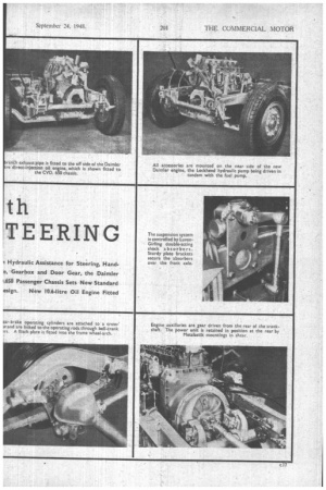
In the engine lubrication system oil is drawn through a gauze screen by a gear pump. which is submerged in the well sump to give freedom from frothing, and is driven from the rear of the crankshaft. An external full-thaw filter is incorporated in the system, together with two magnetic filters, one near the pick up and the other in the main pipe line. The gudgeon pins are lubricated through the connecting rods, and normal cylinder-wall lubrication is augmented by metered spray from a jet hole in the trailing shoulder of the rod.
External piping for the lubrication of the overhead rocker gear has been superseded by internal metered. delivery through the hollow camshaft, oil passing through the journals and oilways in the block and cylinder heads to the base of the centrally drilled rocker-shaft mountings.
The alloy pistons carryfour compression and two oil-control rings, and of particular interest is the introduction of Britest chromium-plated rings for the top c16 The engine is retained in the chassis on three Metalastik mountings, the front mounting being in compression, whilst those at the rear are in shear.
An open-circuit Daimler Fluid Flywheel gives minimum drag at low speeds, operating With less than 2 per cent. slip at high engine speeds. The preselector gearbox, actuated by a gate control on the steering column, is mounted some distance to the rear of the engine, and offset to the near side in line with the crankshaft and the underslung worm drive of the back axle It is rubber insulated to reduce noise.
The universal joints of the forward propeller shall transmit the engine torque through angles of not More than 2 degrees at each end, and the three transmission units are aligned to give constant-velocity operation Hardy Spicer joints are used throughout.. Dimensional modifications have been made to both gearbox and back axle to take the increased torque of the 10.6-litre engine A fully floating rear 'axle is employed with easily detachable driving shafts. Perfect dual/tandem oil seals are provided in the htibs and Angus seals on the driving shafts.
A copventional frame is used, with deep channel side Members, reinforced to the gearbox line te. provide increased resistance to torsion Tubular cross-members afford rigid transverse bracing. The side members are parallel, and, with the repositioning of the engine and gearbox, it has been possible to fit the cross supporting members of the gearbox rectangularly in the frame instead of obliquely, as was forMerly the case.
R.P. fully automatic chassis lubrieation is provided.
Poiitive-camber semi-elliptic springs are fitted to the'. front and rear axles and are controlled by Luvax Girling double-acting shock absorbers. The shackles have hardened pins and can be adjtrsted to take up side play
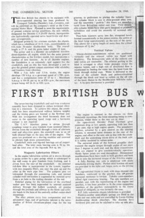
The main interest of the new chassis is centred on the hydraulically operated components, which are dependent on the brake servo accumulator. These comprise the servo hand brake and pedal gear change as standard, and the servo steering and power-operated doors as optional extras. ,
Working fluid is supplied by a Lockheed servo pump, driven from the engine, to dual accumulators arranged in parallel. These consist of single-entry cylinders containing bags of synthetic rubber charged initially to an -air pressure of 400-500 lb. per sq. in. The introduction of fluid into a cylinder to the outside of the bag quickly raises its resistance to a minimum working pressure of 800-900 lb. per sq. in. A cut-out valve restricts the upper working pressure to 1,200 lb. per sq. in.
The hydraulic brake system is essentially similar in principle to the Lockheed full-flow servo, the accumulators becoming operative only below a minimum pump delivery, which in general practice will not occur until -the engine is stopped. Their reserve is sufficient for a number of full brake applications, even if the other subsidiary equipment is in use at the same time. A Purolator element filter between the cut-out valve and the accumulators prevents the passage -of foreign matter and forms connections for this equipment.
The front brake feed is taken from the master cYlinder, which is supplied from the inner compartment of the reservoir independently from the servo system. Operating as-a separate system, the rear brakes are con nected with the end of the control valve, to which fluid is delivered by the pump from the reservoir outer compartment.
A control valve is mounted in a Separate bore and actuated by a balance lever connected to the pedal and master cylinder containing a release valve, movement of which restricts the fluid return port to the supply tank and increases the pressure proportionately. Because the main piston has three times the effective area of the release valve, the boost ratio is 3 to 1 at all pedal pressures. Return of the brake pedal opens the return port fully and restores free circulation.
Identical servo units are used for the power operation of both the hand brake and the gear-change pedal. They are designed for a boost ratio of 3 to I, the maximum work of which they are each capable being 3,693 in.-lb. at 1,000 lb. per sq. i.n. accumulator pressure.
Operation is based on the balanced-pressure-valve principle, and fluid flow does not take place until a pull on the lever or pedal rod moves the release valve to a position in which the return port is closed and the reducing valve is opened. Fluid from the.accumulator then increases the pressure behind the main piston, which is positively connected to the operating rod at one end and to the centre of the balance link'carrying the
cl 8 control-valve plunger and lever rod at the other end. immediately the pressure on the main piston balances the reaction of the release valve, the latter opens -the return port and the balance valve closes the connection to the accumulator.
With the hand-brake system the process is repeated with further movement of the lever. In bOth systems a return to the released position cuts off the accumulator connection and opens the return port to prevent a buildup of pressure in the control valve while not in operation. The mechanical linkage permits non-servo operation if the accumulator pressure fails. Should there be a decrease in servo pressure when the vehicle is parked, the hand brake will be held by the ratchet.
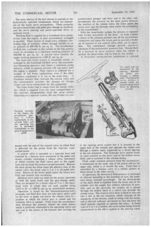
A three-start worm-and-nut mechanism is retained in the steering servo system but it is situated in the upper half of the column and operates the rocker arm through a hollow shaft, supported by a thrust bearing in the nut extension. The hydraulic servo piston forms an outer annulus on the lower end of the hollow worm shaft, and is enclosed in the column casing.
Fluid, under constant pressure from the accumulator, is maintained on the under side of the piston and on the upper side, which is of double the area. Fluid feed is controlled by a balance valve of a similar pattern to those found in the other servos.
In operation, the downward fluid pressure is increased or relieved according to the direction of turn, the assistance being reversed accordingly. On the down-stroke of the shaft, fluid is expelled from the lower end of the cylinder into the supply line without reduction of pressure, and on the up-stroke the surplus oil is passed through the hollow shaft to a return line through the casing sump. The control-valve lever is fitted at one end into a slot in the nut extension which, because of the angularity of the threads, tends to swing with the worm, and is allowed sufficient movement to turn the lever the small amount required to operate the valve. A boost ratio of 6 to 1 is available, the servo action being directly proportional to the effort applied to the steering wheel